
Step down voltage converter 5v with transistor BC337

The step-down voltage converter circuit, also known as a buck converter, is designed to efficiently reduce a higher DC voltage to a lower DC voltage while maintaining regulation. This type of circuit is particularly advantageous in applications requiring a stable output voltage from a higher input voltage source, such as battery-powered devices, power supplies, and various electronic systems.
At the core of the buck converter is a switching element, typically a transistor, which rapidly turns on and off to control the energy transfer from the input to the output. The switching action is regulated by a feedback mechanism that monitors the output voltage and adjusts the duty cycle of the switching element accordingly. This feedback loop ensures that the output voltage remains stable despite variations in the input voltage or load conditions.
The circuit generally consists of several key components: the input capacitor, switching transistor (often a MOSFET), a diode, an inductor, and an output capacitor. The input capacitor smooths the input voltage and provides a stable supply to the switching element. The inductor stores energy when the transistor is on and releases it to the output when the transistor is off, while the diode ensures current flows in the correct direction during the off phase.
The output capacitor is crucial for filtering the voltage ripple generated during the switching process, providing a smooth DC output voltage. The design of the inductor and capacitors must be carefully selected based on the desired output voltage, current requirements, and switching frequency to optimize performance and efficiency.
In summary, the step-down voltage converter circuit is a vital component in modern electronic designs, offering an efficient means to convert and regulate voltage levels within various applications. Its ability to handle high efficiency and compact size makes it a preferred choice for many electronic devices.The circuit decreases the size voltage or Stepdown Voltage converter circuit be dc regulated circuit model switching converter. The that make voltage output. 🔗 External reference
Related Circuits
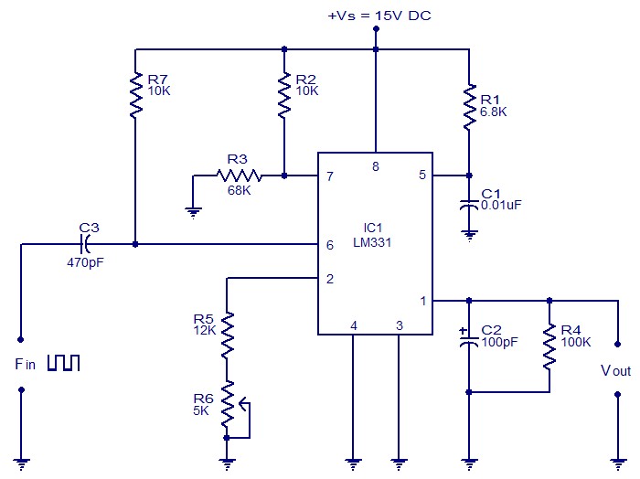
The following circuit illustrates a Frequency Voltage Converter Circuit. This circuit is based on the LM331 IC and operates with a supply voltage of 15V DC. The Frequency Voltage Converter Circuit utilizes the LM331 integrated circuit, which is designed for...
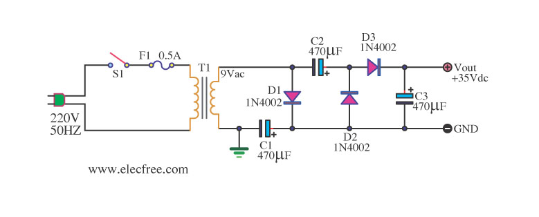
Simple AC to DC converter 9VAC to 35VDC. This is a basic example of an AC to DC converter model designed to be straightforward. It modifies 9VAC input to produce 35VDC output, depending on various factors. The AC to DC...
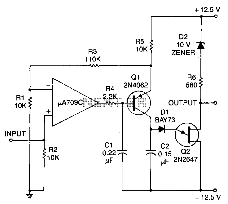
This circuit consists of a UJT oscillator where the timing charge capacitor C2 is linearly dependent on the input signal voltage. The charging current is determined by the voltage across resistor R5, which is precisely controlled by the amplifier....
This converter allows reception of signals below 500 kHz on a 3.5 to 4 MHz HF receiver. It should therefore be useful for those with receivers that do not receive the lower frequencies. Again the converter uses the popular...
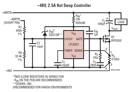
The LTC4251, LTC4251-1, and LTC4251-2 are negative voltage Hot Swap controllers designed to enable the safe insertion and removal of a board from a live backplane. The output current is managed through three stages of current limiting: a timed...
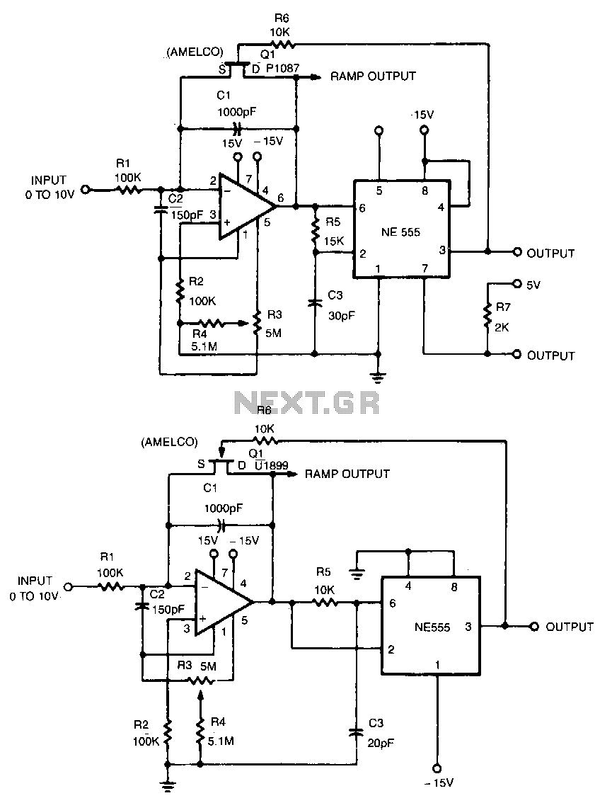
This linear voltage-to-frequency converter achieves good linearity over the range of 0 to -10 V. Its mirror image provides the same linearity over the range of 0 to +10 V; however, it is not compatible with DTL or TTL. The...