
Step Up PSU for LCD

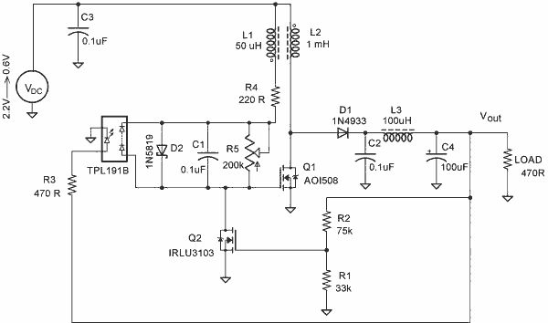
The design of a DC/DC converter for the Optrex DMC50264N LCD module involves converting a low input voltage (3V to 5V) to a higher output voltage of +24V. The MC34063 is a versatile DC-DC converter IC that can be configured as a step-up (boost) converter, making it suitable for this application. The typical circuit configuration includes an inductor, a diode, and output capacitors in addition to the MC34063.
In the circuit, the input voltage is connected to the inductor, which stores energy when the switch inside the IC is closed. When the switch opens, the energy stored in the inductor is released to the output through the diode, raising the voltage to the desired level. The output capacitor smooths the voltage, ensuring a stable supply to the LCD module.
Due to the low current requirements of the LCD, a smaller SMD inductor would typically be preferred for compactness. However, in this case, a larger inductor was used, measuring about 1 cm in height, likely due to constraints in component availability. The choice of inductor affects the efficiency and response time of the converter, so careful consideration of the inductor's specifications is essential.
Overall, the MC34063-based boost converter effectively provides the necessary +24V bias for the Optrex DMC50264N LCD module, making it a practical solution for applications where only low input voltages are available. Proper layout and component selection will ensure reliable operation and performance of the circuit.To start old Optrex DMC50264N LCD module you need to get +24V LCD bias voltage Where to get it if you have only low voltage 3 5V As LCD module drains very low current, it is possible to build very small DC/DC converter. There are lots of chips designed for this. I used MC34063, as I already had few of them in some old trash boards. The schem atics are typical, used from datasheet. As the current is very low, it is possible to use very small SMD inductance. I didn`t find very small, so I used quite big- about 1cm tall 🔗 External reference
Related Circuits

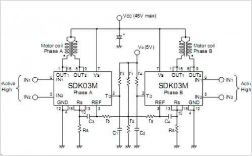
This document outlines the design process of a control circuit for a stepper motor. Given the characteristics of the stepper motor, the control circuit was developed as a state machine that transitions through four output states depending on two...
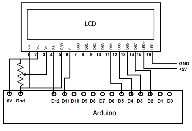
To achieve this, the first step involves establishing the necessary physical connections between the Arduino board and the LCD. Following this, code must be written to display the desired text on the LCD. LCDs have become the standard means...
This circuit measures the distance traveled during a walk. The hardware is housed in a small box that can be placed in a pants pocket. The display is designed as follows: the leftmost display D2 (the most significant digit)...
A simple blocking oscillator circuit can be utilized to increase voltage by leveraging the properties of coil inductance (V = L di/dt). Such a circuit is illustrated in Figure 1. The blocking oscillator circuit is a type of oscillator that...
A step-up converter followed by an LDO regulator provides improved battery life compared to a traditional SEPIC design when powered by a single lithium-ion cell. The circuit design features a step-up (boost) converter that elevates the input voltage from a...
The SM5023 series consists of 3rd overtone crystal oscillator module integrated circuits (ICs). These ICs are equipped with built-in oscillator capacitors that provide excellent frequency response. The cutoff frequency can be configured using an external feedback resistor (Rfo), allowing...