
Stepper motor controller Based On The PIC16F84A IC

The stepper motor controller circuit employs the PIC16F84A microcontroller, which serves as the central processing unit for controlling the stepper motor's operation. The PIC16F84A is an 8-bit microcontroller with a 14-bit instruction set architecture, allowing for efficient control algorithms to be implemented.
The circuit typically includes a driver stage, which often consists of one or more transistors. These transistors are crucial as they amplify the control signals from the microcontroller to provide sufficient current to the stepper motor coils. The choice of transistor is important; commonly used transistors include N-channel MOSFETs or bipolar junction transistors (BJTs), depending on the current requirements of the motor.
The control logic for the stepper motor can be implemented in various modes, such as full-step, half-step, or microstepping, which can be programmed into the PIC16F84A. The microcontroller generates the necessary pulse sequences to energize the motor coils in the correct order, resulting in precise control of the motor's rotation.
Additional components in the circuit may include resistors, capacitors, and diodes. Resistors may be used for current limiting, while capacitors can help stabilize the power supply and filter out noise. Diodes are often included to protect the circuit from back EMF generated by the motor when it is turned off, ensuring the longevity of the components.
The power supply for the circuit should be chosen based on the voltage and current specifications of the stepper motor, ensuring that it meets the operational requirements without exceeding the ratings of the microcontroller and driver components. Proper layout and grounding techniques should also be employed to minimize electromagnetic interference and ensure reliable operation of the stepper motor controller.The following circuit shows about Stepper motor controller. This circuit based on the PIC16F84A IC. Features: transistor is used to drive the .. 🔗 External reference
Related Circuits
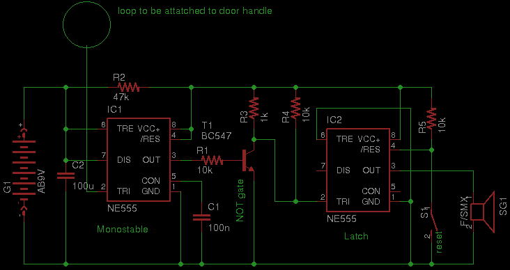
Security has become a significant concern in today's world, leading to the availability of various security gadgets. This document introduces a simple touch alarm designed specifically for doors with metallic handles. The alarm functions exclusively on metallic handles and...
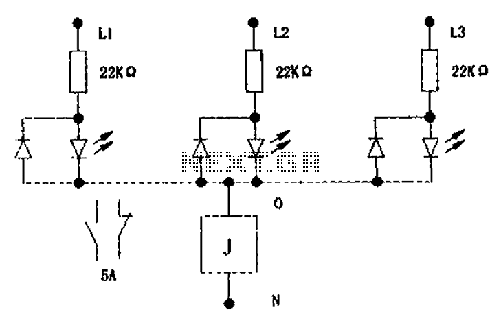
The circuit illustrated below activates a small relay (J) when there is an imbalance in any one phase of a three-phase circuit. This relay triggers an external control contact, which immediately disconnects the power supply to the main circuit...
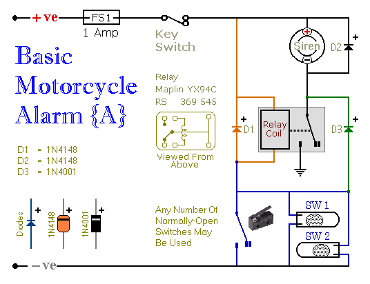
These are two easy-to-build relay-based alarms that can be used to protect motorcycles, among other applications. Using relays with 6-volt coils will safeguard a "Classic Bike." Both alarms are compact, with completed boards occupying approximately half a cubic inch...
The 555 IC is wired as an astable and the frequency is constant and independent of the duty cycle, as the total resistance (R charge + R discharge, notice the diode) is constant and equal to 22Kohm (giving a...
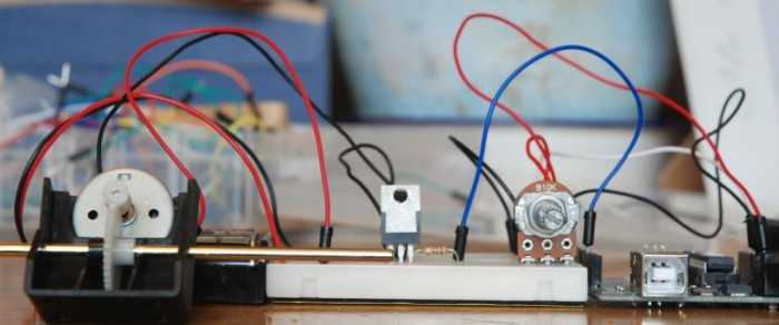
A quick circuit showing how to control the speed of a DC motor with a potentiometer with your Arduino board. Also shows how to use a TIP120 transistor to allow the Arduino control a larger power supply. This circuit utilizes...
L293D Schematic diagram. The L293D division supplies power to the chip and its controlled motors, enabling the connection of motors with a higher voltage power supply than the chip itself. The separation of power circuits and electric motors may...