
Stepper Motor Controller

Stepper motors are widely utilized in applications requiring precise control of movement and positioning. They operate by dividing a full rotation into a series of discrete steps, allowing for fine control over angular position. The motor's ability to hold its position without the need for continuous power makes it ideal for applications such as 3D printers, CNC machines, and robotics.
The driving circuit for a stepper motor typically includes a microcontroller, which generates the necessary control signals to drive the motor. The microcontroller sends pulses to a driver circuit that powers the motor coils in a specific sequence, causing the rotor to move in precise increments. This sequence is often referred to as "stepping," and the number of steps per revolution is a critical parameter that defines the motor's resolution.
In a typical configuration, the stepper motor will have multiple coils (phases), and the control circuit will energize these coils in a specific order to achieve the desired rotation direction and speed. The use of H-bridge configurations in the driver circuit allows for bidirectional control of the motor, enabling it to rotate clockwise or counterclockwise based on the input signals.
For enhanced performance, microstepping techniques can be employed, which involve controlling the current through the motor coils to create intermediate steps. This results in smoother motion and increased resolution, making it suitable for applications that require high precision.
In summary, the combination of a stepper motor with an appropriately designed driving circuit offers an effective solution for applications demanding accurate position control, with the added benefits of low cost and simplicity in implementation.Stepper motor gives a simple, low cost, and accurate position control. Stepper motor can be driven by circuit mounted close to the motor, and controlled by a. 🔗 External reference
Related Circuits
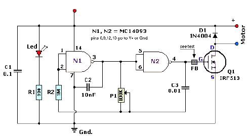
A quad 2-input NAND Schmitt trigger circuit can be designed using the MC14093 CMOS type IC, which serves as a simple pulse width modulation (PWM) controller electronic project. This PWM controller is straightforward and requires only a few external...
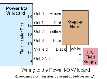
For optimal efficiency, set MAX_STEPPERS to the number of stepper motors being controlled, with a maximum limit of four. Motors are identified by indices 0, 1, 2, and 3. On the QCard, there is a trade-off between the number...
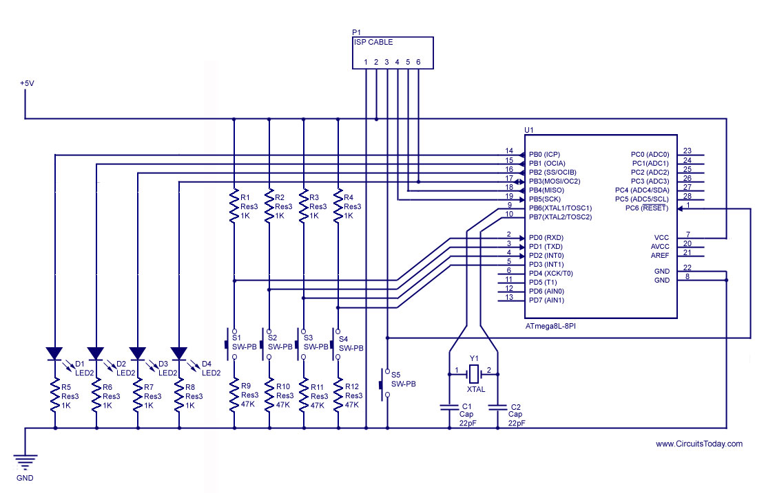
How to handle digital input/output (I/O) in AVR microcontrollers is explained using basic programs and circuits to illuminate an LED, generate a stepper motor sequence, read a push-button switch, and implement key debouncing. The handling of digital I/O in AVR...
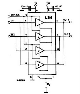
The IC H-Bridge DC motor driver L298 contains two H-Bridge circuits, allowing it to drive two DC motors simultaneously. Each H-Bridge circuit can deliver currents up to 2A. When used in parallel, the L298 can provide a total current...
This is a straightforward, cost-effective Hi-Fi quality power amplifier. It can be constructed in five different configurations, as indicated in the table, ranging from 20 W to 80 W RMS. This Hi-Fi quality power amplifier is designed to deliver high...
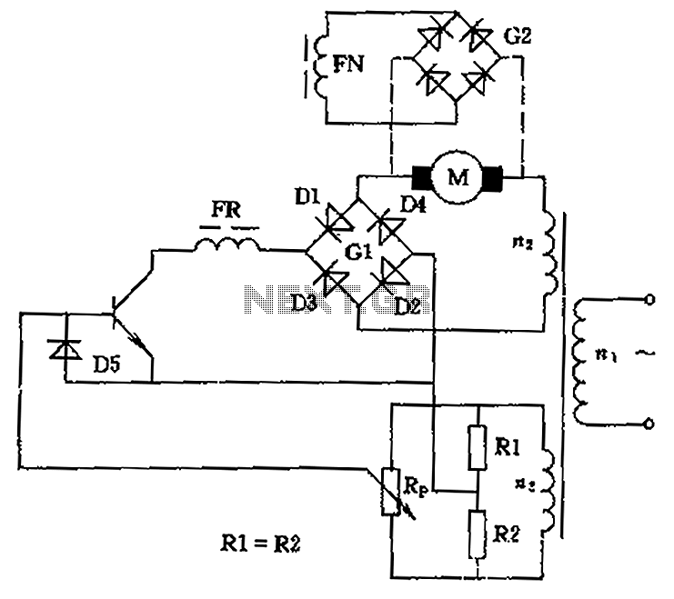
The circuit is designed to control the speed and direction of low-power DC motors, including series and shunt motors. It utilizes a rectifier bridge (G1) connected in series with the motor and linked to the secondary winding (n2) of...