
STEPPER MOTOR DRIVER

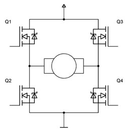
This circuit design effectively demonstrates the control of a stepper motor using discrete components, specifically four IRF510 power FETs, which are known for their high efficiency and fast switching capabilities. The CMOS counter serves as the primary control unit, generating the two-phase quadrature signals necessary for stepper motor operation.
The four FETs are arranged in a configuration that allows them to alternate the current flow through the motor windings, enabling precise control over the motor's position and speed. The IRF510 FETs are selected for their ability to handle significant power levels, making them suitable for driving the stepper motor without overheating or suffering from performance degradation.
In this application, the CMOS counter generates square wave outputs that are fed to the gates of the FETs. The two-phase output provides the required phase shift that allows the stepper motor to increment its position smoothly. The use of a CMOS counter is advantageous due to its low power consumption and high noise immunity, which enhances the reliability of the circuit.
The stepper motor, sourced from a discarded floppy disk drive, typically consists of multiple coils arranged in phases that correspond to the quadrature signals generated by the CMOS counter. This recycling of components not only reduces costs but also promotes sustainable practices in electronics design.
In summary, this circuit exemplifies an efficient method for controlling a stepper motor using basic electronic components, highlighting the practicality of utilizing available parts for experimentation and learning in the field of electronics.In this circuit, four IRF510 power FETs are driven by a CMOS counter to generate the necessary two-phase drive quadrature. Although ICs are available to do this, this approach is handy for the experimenter because it uses commonly available parts.
The stepper motor was taken from a discarded floppy-disk drive.. 🔗 External reference
Related Circuits
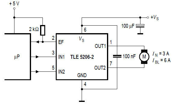
Stepper motor control circuit diagram using TLE5206 for remote control car. The stepper motor control circuit is designed to manage the operation of a stepper motor, specifically utilizing the TLE5206 integrated circuit. This circuit is particularly suitable for applications in...
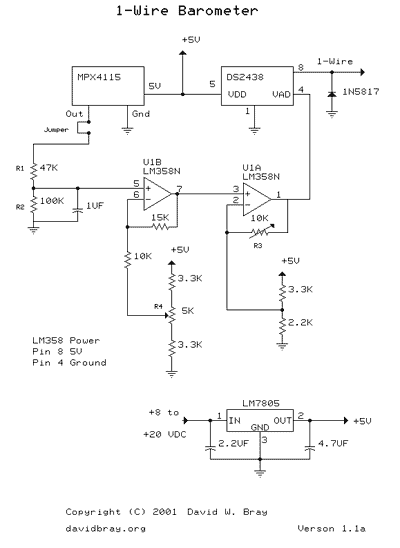
This design uses a Motorola MPX4115 Silicon Pressure Sensor, a Dallas Semiconductor DS2438 Smart Battery Monitor (to perform 1-Wire analog to digital conversion), an operational amplifier, a voltage regulator, a diode, and several resistors and capacitors. The circuit requires...
With this simple project, you can have balanced lines too, simply adapting the unbalanced inputs and outputs of your hi-fi gear to become balanced, and then back to unbalanced at the other end. You can even be extra cunning,...
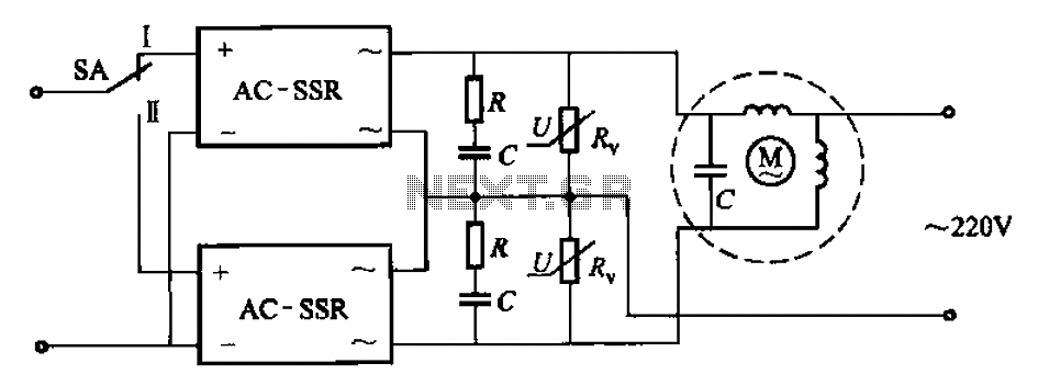
The circuit illustrated in Figure 3-14 features a SA switch positioned in the work state, allowing for motor operation. When the SA switch is set to the reverse position, the motor's direction is inverted. Additionally, an over-voltage protection element...
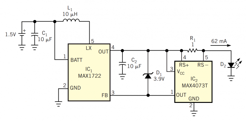
Although white LEDs are common in a variety of lighting applications, their 3 to 4V forward-voltage drop makes low-voltage applications challenging. Charge pumps and other ICs are available for driving white LEDs, but they generally don't work with the...
The project involves a DC geared motor intended for use in a suitcase carrier. Two motors were purchased from Pololu at a cost of approximately $100. The selection process included discussions among team members, followed by consultation with Dr....