
Stepper Motor Generator

The circuit design utilizes a stepper motor as an efficient generator capable of producing substantial voltage output even at minimal mechanical input. The stepper motor's unique property of generating high voltage at low speeds makes it particularly advantageous for applications where manual cranking is feasible. The inclusion of two bridge rectifiers, each formed by four 1N4148 diodes, ensures effective conversion of the generated alternating current (AC) into direct current (DC) suitable for charging the storage capacitor.
The 4700 µF capacitor serves as an energy reservoir, allowing for the storage of electrical energy generated by the motor. This stored energy can then be utilized to power a super-bright LED, which is a critical component of the hand-cranked torch circuit. The choice of LED provides high luminosity while maintaining energy efficiency. The circuit offers two operational modes for the LED, controlled by the selection of series resistors. The 390-ohm resistor configuration maximizes brightness, suitable for immediate illumination needs, while the combination of a 22k-ohm resistor with the 390-ohm resistor allows for extended runtime at reduced brightness, ideal for prolonged use without rapid depletion of stored energy.
It is essential to monitor the current and voltage levels within the circuit to prevent exceeding component ratings. The LED's current should not surpass 20 mA to avoid damage, and the capacitor voltage must remain below 25 volts to ensure safe operation. Adjustments to the series resistor values can be made to accommodate variations in the generated voltage and current, ensuring optimal performance and longevity of the components.
This stepper motor generator circuit is versatile and can be employed in various scenarios, including emergency lighting, hobby projects, or as a backup power source in low-light environments. Its design emphasizes simplicity, efficiency, and adaptability, making it an excellent choice for applications requiring portable and sustainable lighting solutions.Any stepper motor can be used as a generator. In contrast to other generators, a stepper motor produces a large induced voltage even at low rotational speeds. The type used here, with a DC resistance of 2G—60 per winding, can generate more than 20 V when turned by hand, without any gearing.
The circuit diagram for a hand-cranked torch` shows h ow you can use a stepper motor as a generator. A supplementary circuit stores the energy. Two bridge rectifiers, each made up of four 1N4148 diodes, charge the 4700 µF capacitor. The super-bright (white) LED is driven either via a 390- resistor (Power Light), or via 22 k in series with 390 . In the latter case, the LED is not as bright, but it stays on longer. You must restrain yourself when cranking the dynamo, since in the bright` setting it is possible to exceed the rated LED current of 20mA, while in the long` setting it is possible to exceed the rated capacitor voltage of 25 V.
If necessary, adjust the value of the LED series resistor. The lamp is bright enough for reading in complete darkness. The stepper motor generator is thus ideal for spies, thieves and children who want to read under the bedcovers. You could also keep it handy in your hobby room, in case of a short circuit. 🔗 External reference
Related Circuits
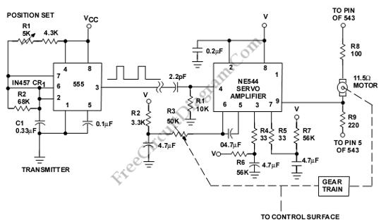
This is a servo system controller circuit designed for remote control of a servo motor. The circuit utilizes a 555 timer and requires only six additional components. The servo system controller circuit operates by generating a pulse-width modulation (PWM) signal,...
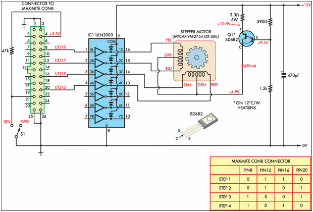
Designing and implementing this circuit was an exciting endeavor. The design of the interface involved learning how to control a device from a computer. A parallel port cable was utilized for this purpose, enabling instant control of the stepper...
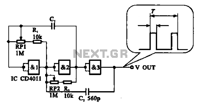
An adjustable pulse generator circuit is presented, which produces a periodic signal with independently adjustable pulse widths. The electrical path allows for modifications to the signal period through the adjustment of RP1. Additionally, RP2 can be altered to change...
Figure 2-32 (a) illustrates the time control diagram for a motor operated by switch S1. When S1 is set to position 1, the power driver circuit supplies current to the motor, enabling it to run. When S1 is switched...
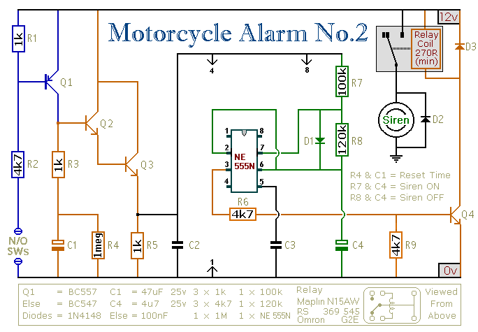
This circuit provides an intermittent siren output with an automatic reset function. It can be manually activated using a key switch or a concealed switch, and it can also be configured to engage automatically when the ignition is turned...
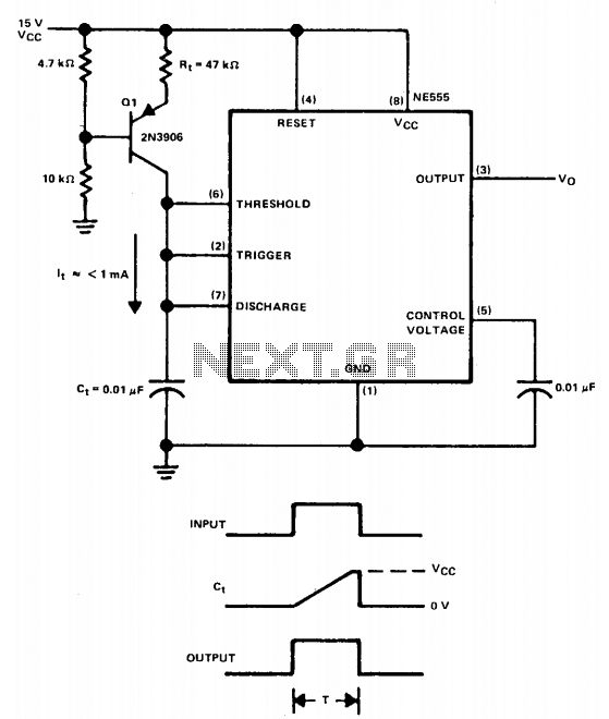
The linear charging ramp is particularly beneficial in applications requiring linear voltage control. Potential uses include long-duration voltage-controlled timers, voltage-to-pulse width converters, and linear pulse width modulators. Q1 acts as the current source transistor, providing a constant current to...