
PWM motor speed controller

The circuit operates by leveraging the characteristics of the CD4093 Schmitt trigger IC, which provides a stable output even with noisy input signals. The oscillator configuration formed by U1a generates a square wave signal whose frequency and duty cycle can be adjusted by changing the values of the timing components connected to it, typically resistors and capacitors. This square wave output is then buffered by U1b, U1c, and U1d to ensure that it can adequately drive the gate of the MOSFET Q1 without introducing significant signal degradation.
The MOSFET acts as a switch that controls the power delivered to the DC fan motor. When the gate of the MOSFET receives a high signal from the buffered output of the oscillator, it turns on, allowing current to flow through the motor. The speed of the motor is directly proportional to the duty cycle of the PWM signal; a higher duty cycle results in a higher average voltage across the motor, leading to increased speed. Conversely, a lower duty cycle reduces the average voltage and decreases the motor speed.
Diode D3 is crucial for protecting the circuit from back EMF generated by the inductive load of the motor when it is switched off. This back EMF can cause voltage spikes that may damage the MOSFET and other components. D3 allows the current generated by the motor's inductance to circulate safely, preventing damage and ensuring reliable operation.
Overall, this circuit effectively meets the specified requirements for a DC fan motor controller, providing adjustable speed control through a simple and robust design.This circuit is designed as per a request made by Mr Vinoth from India. His requirement was a 12V/5A DC fan motor controller. I think this circuit is sufficient for this purpose. Quad 2 input Schmitt trigger IC CD4093 is the heart of this circuit. Out of the four Schmitt triggers inside the 4093, U1a is wired as an oscillator with adjustable duty cycle. The U1b, U1c, U1d buffers the output of the oscillator to drive the switching MOSFET Q1. The MOSFET drives the DC motor according to the switching pulse obtained from the oscillator. When R1 is varied the duty cycle varies and so do the speed of the motor. Diode D3 acts as a freewheeling diode. 🔗 External reference
Related Circuits
M1 is a stepper motor salvaged from an old disk drive. It features five pins: common, coil 1, coil 2, coil 3, and coil 4. The resistance measured between the common pin and each coil is approximately 75 Ohms....
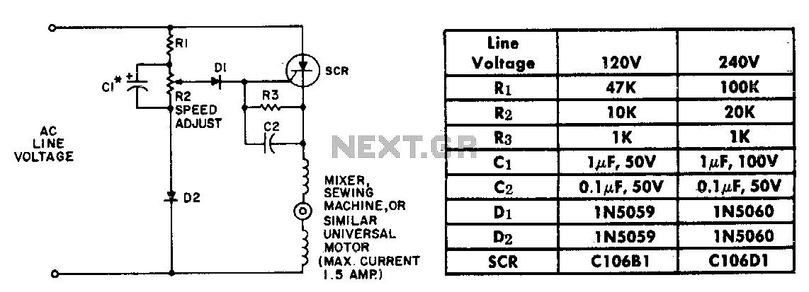
The resistor-capacitor network R1-R2-C1 generates a ramp-type reference voltage that is superimposed on an adjustable DC voltage controlled by the speed-setting potentiometer R2. This reference voltage, available at the wiper of R2, is compared against the residual counter electromotive...
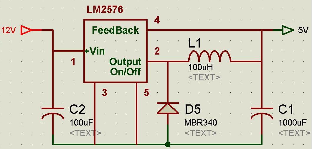
A regulated and noise-free power supply voltage is essential for microcontrollers and other components such as amplifiers, filters, and GPS devices. Voltage surges in the supply voltage can permanently damage embedded systems. A voltage regulator must maintain the output...
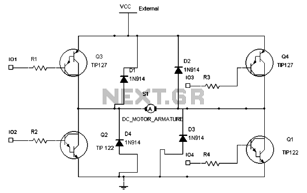
To maintain a constant speed of the motor under varying load conditions, a control application circuit is required. An H-Bridge circuit can be utilized to manage both the speed and direction of the motor. The accompanying diagram illustrates the...
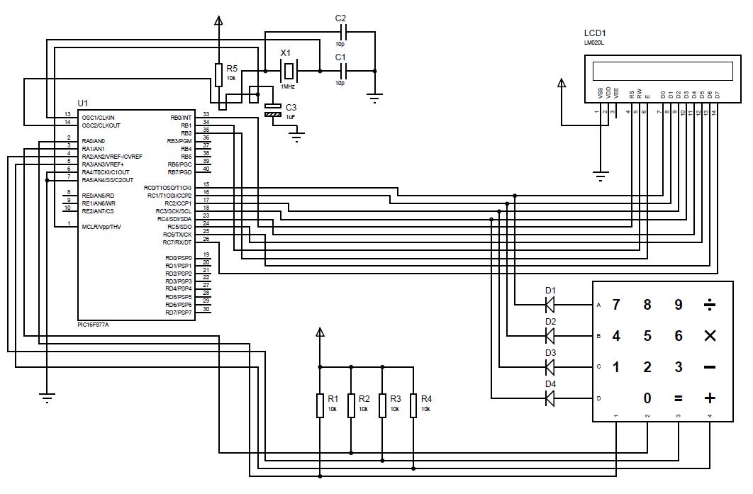
A beginner or hobbyist is seeking to learn more about microcontrollers. The objective is to display an output on an LCD when a button on the keypad is pressed. To achieve the desired functionality of displaying output on an LCD...
This Project is used to control a single phase Motor from any where in the world through the telephone. The circuit consists of a DTMF tone detector and a powerful 8 bit Microcontroller AT89S52. The Microcontroller senses the DTMF...