
Stepping Motor Driver

This circuit is designed for controlling a stepper motor with features that allow for precise movement in both forward and reverse directions, as well as maintaining its position when powered. The operation modes include FULL STEPS FORWARD and FULL STEPS REVERSE, which enable the motor to move incrementally by energizing the motor coils in a specific sequence.
The ACTIVE HOLD feature is essential for applications where the motor must maintain its position without moving, ensuring that the motor does not lose its holding torque when not actively stepping. The POWER OFF or RELEASED mode allows for the motor to be powered down completely, which can be useful for reducing energy consumption when the motor is not in use.
In the event that the motor does not turn, a troubleshooting step involves swapping the leads of one of the two coils. This adjustment can correct the phase of the motor coils, which is crucial for proper operation. The circuit incorporates an EN (enable) signal that controls the activation of the motor. To modify the behavior of the EN signal, the circuit can be reconfigured using an XNOR gate. This logic gate will allow for the reversal of the EN signal sense, enabling flexibility in the control logic depending on the system requirements.
Overall, the circuit is robust against motor transients, which are sudden changes in voltage or current that can occur during motor operation, ensuring reliable performance in various applications. The design considerations make it suitable for environments where precise motor control is necessary.The circuit is not particularly susceptible to motor transients and supports FULL STEPS FORWARD, FULL STEPS REVERSE, ACTIVE HOLD, and POWER OFF aka RELEASED. If the motor does not turn then swap around the leads of ONE of the two coils. To reverse the sense of the EN signal simply rework the circuit around an XNOR gate. 🔗 External reference
Related Circuits
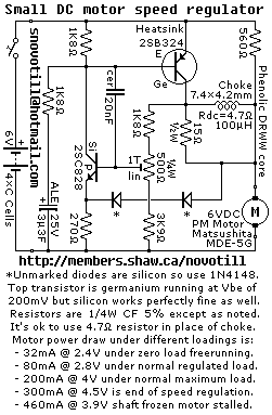
Reverse engineered circuit diagram of a motor speed regulator out of a portable pocket tape recorder containing a single motor for all functions. This circuit works amazingly well, keeping the motor speed constant regardless of shaft load and battery...
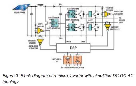
Both help improve efficiency and protect micro-inverters in photovoltaic (PV) solar applications. In 2009, the residential solar photovoltaic (PV) inverter market represented 90 percent of the total PV. The integration of micro-inverters in photovoltaic solar applications has significantly enhanced system...
The diac is a common component used to trigger triacs. The construction of a diac is similar to that with a transistor, but with both junctions doped to similar levels so that the two junctions' reverse breakdown characteristics are...
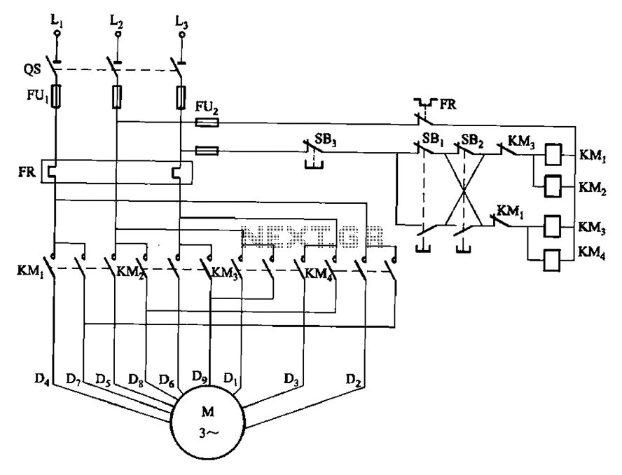
The circuit depicted in Figure 3-112 features two operation buttons: SBi, which serves as the first speed operation button, and SBz, which operates the second speed class. Both buttons facilitate two speeds in the same direction. The circuit design incorporates...
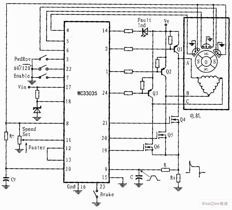
The presented three-phase application circuit features a motor controller circuit connection diagram that operates using a full-wave six-step method. The power switch is a Darlington PNP type, while the lower power switch is an N-channel power MOSFET. Each device...

This figure illustrates a block diagram of modern automated systems that incorporate closed-loop feedback for motion control. These systems typically feature a servo system consisting of feedback elements and a motor driver, which work together to provide accurate and...