
Stereo Audio Amplifier with TDA2616

The described power amplifier project reflects a journey through basic electronics and the evolution of design principles. The initial amplifier, built with discrete transistors, likely utilized a common emitter configuration to achieve amplification. The limited power output might have been attributed to the choice of transistors and circuit design, which often require careful selection of components to optimize performance.
The introduction of the TDA1524 integrated circuit for tone and volume control demonstrates a pivotal moment in the design process. The TDA1524 is a versatile IC capable of providing both pre-amplification and signal conditioning, which would significantly enhance the audio quality by allowing for precise control over bass, treble, and overall volume levels. This addition likely improved the overall fidelity of the sound produced by the amplifier, making it more enjoyable for listening.
The decision to transition to an integrated circuit for the new power amplifier design in 2006 indicates an understanding of modern electronic design practices. Integrated circuits offer several advantages, including reduced size, lower cost, and increased reliability due to fewer interconnections and external components. The design of the new amplifier would involve selecting an appropriate power amplifier IC, which would ideally provide higher output power and efficiency compared to the earlier transistor-based approach.
The schematic for the new power amplifier would typically include the chosen power amplifier IC, input and output capacitors, feedback resistors, and possibly a heat sink to manage thermal dissipation. Power supply considerations would also be crucial, ensuring that the amplifier operates within its specified voltage and current ratings. Additional features such as protection circuitry, including short-circuit and thermal protection, would enhance the reliability of the final design.
In summary, the evolution from a basic transistor amplifier to a more sophisticated integrated circuit design illustrates the advancements in electronic engineering and the importance of component selection in achieving desired performance outcomes in audio amplification.I built my first power amplifier when I was still in secondary school. The circuit was made of transistors, didn`t provide much power and had an ugly PCB. Around the same time I got access to a datasheet of TDA1524, a tone/volume control circuit, and I decided to use it to build a pre-amplifier, to improve the quality of the sound coming out of the amplifer. Both circuits worked well for almost a decade but the old amplifier was never up to my expectations. In 2006 I decided that it was time to build a real power amplifier, this time based on an integrated circuit to reduce the number of external components and cost
🔗 External reference
Related Circuits
The following circuit illustrates the IC BA1404 used in a stereo FM transmitter circuit diagram. Features include ease of construction, making it accessible for anyone to build. The BA1404 is a versatile integrated circuit designed specifically for FM transmission applications....
The 200 MHz JFET possesses the following characteristics: 1. Low crossmodulation 2. High large-signal handling capability 3. No requirement for neutralization 4. Automatic Gain Control (AGC) managed by adjusting the biasing of the upper. The 200 MHz Junction Field Effect...
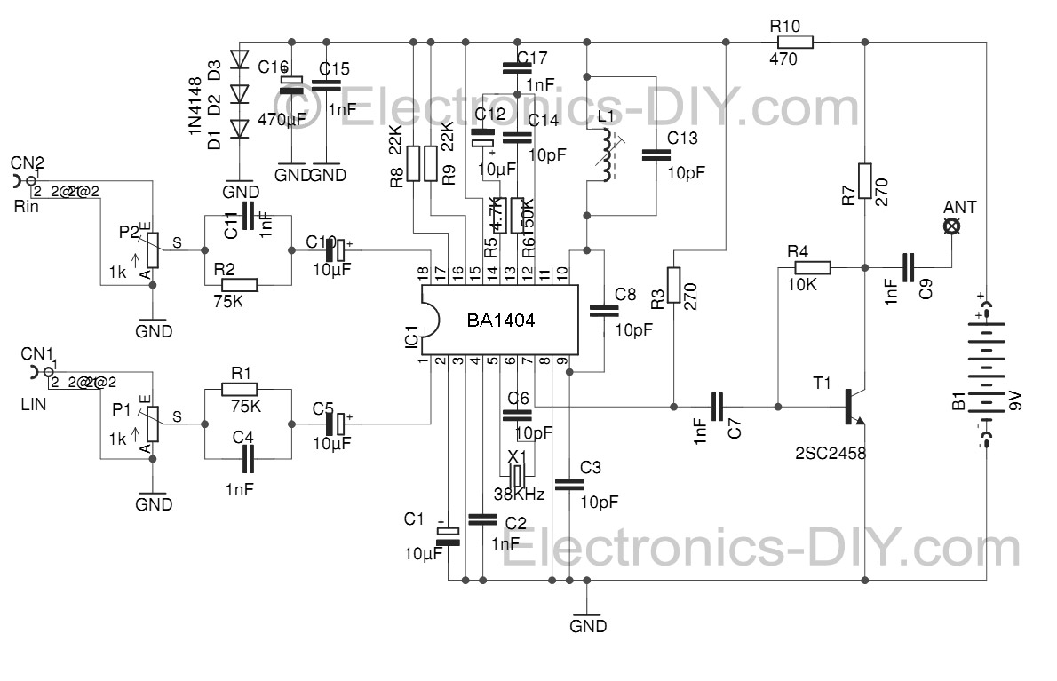
This Stereo FM Transmitter with BA1404 enables the creation of a mini stereo FM station, allowing for wireless audio broadcasting throughout a home. It provides a straightforward method for establishing an audio link without the need for complex wiring....
Here you will find a design for a headphone amplifier. The supply voltage is 12 volts. I have the circuit taken as 5 watt amplifier, but after a test showed that with a little speaker to the amplifier power...
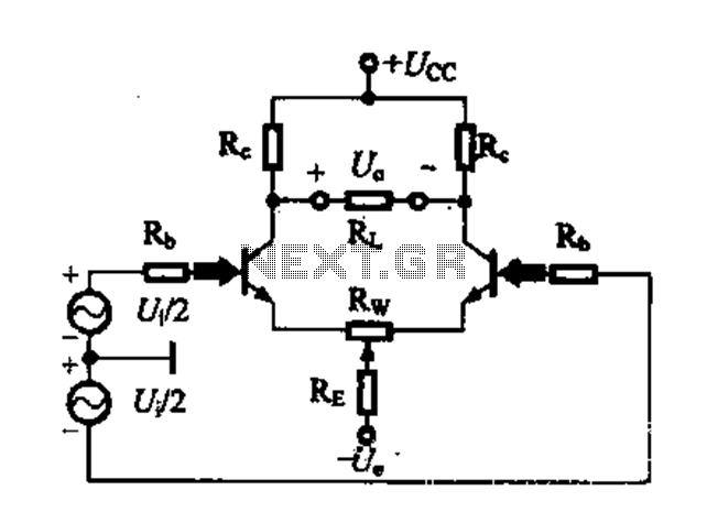
A differential amplifier circuit can be configured in four different connection methods, allowing for a comparison of characteristics such as gain and common-mode rejection ratio (CMRR). This analysis focuses on symmetrical circuits and their performance in handling common-mode signals. The...
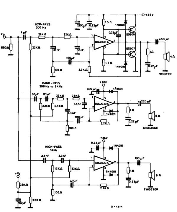
A simple multiway active speaker audio system can be designed using the TDA2030 audio IC. This TDA2030 active speaker audio system circuit is created to deliver optimal acoustic performance, as each loudspeaker is specifically designed and optimized for a...