
Stereo balance meter

The circuit described involves an amplifier with a built-in indicator system that utilizes LEDs to provide visual feedback on the balance of audio output. When the amplifier is switched to mono mode, it combines the left and right audio channels into a single channel. This mode is essential for adjusting the balance control, which is a variable resistor that alters the relative volume levels of the left and right channels.
In this configuration, the balance control is adjusted to achieve equal illumination of both LEDs, indicating that the audio output is balanced. The LEDs serve as visual indicators, where each LED corresponds to one of the audio channels. When both LEDs shine with equal brightness, the output is perfectly balanced, ensuring that the sound is evenly distributed to the speakers.
The amplifier's circuitry likely includes a microcontroller or a simple comparator circuit that monitors the output levels of each channel. This system can be designed to provide feedback in real-time, allowing for precise adjustments. The use of mono mode simplifies the balance adjustment process by eliminating the complexities of stereo sound, making it easier for users to achieve the desired auditory experience.
Once the balance control is set correctly, the amplifier can be switched back to stereo mode, allowing for a full stereo sound experience with the channels properly balanced. This feature is particularly useful in audio setups where channel imbalances can significantly affect sound quality and listener experience.To use the indicator, switch the amplifier to mono mode and adjust the balance control until both LEDs are equally illuminated. The amplifier is now in perfect stereo mode balance.
Related Circuits
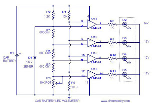
This circuit is a practical device that, when installed in a vehicle, displays the voltage of the car battery using an LED dot display. The meter circuit utilizes four comparators formed from a quad op-amp, specifically the LM324. The...
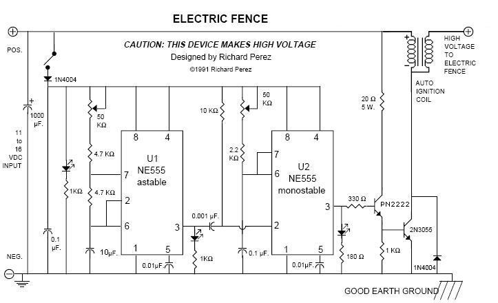
An electric fence perimeter protection circuit designed to operate on batteries and provide configurable pulses of up to 20 kV to safeguard a tent perimeter against bears or other wildlife in the outdoors. The device utilizes two 555 timer...
In the circuit below, a quad voltage comparator (LM339) is utilized as a simple bar graph meter to indicate the charge condition of a 12-volt lead-acid battery. A 5-volt reference voltage is connected to each of the positive inputs...
The device employs a microammeter with a full-scale deflection of 50 µA and a resistance of 2 kilohms. The upper limit of the voltmeter's measuring range is 1 V, and within the range of 0.2 to 1 V, the...
The AVO VCM 163 is a tube tester capable of measuring tube electrode currents, such as plate and screen currents, as well as mutual conductance simultaneously. It is the most advanced tube tester developed by AVO. The voltages applied...
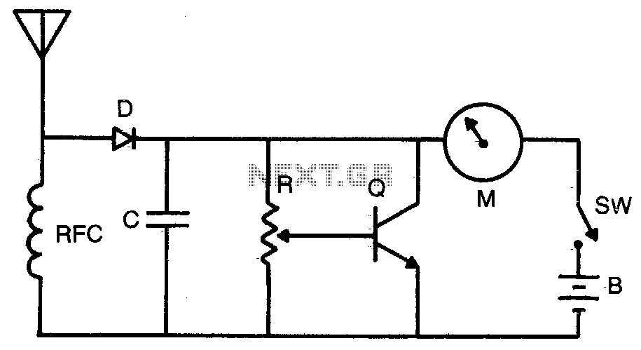
Increased sensitivity provides field strength readings from low-power transmitters. The operating range is 3-30 MHz. To operate, adjust R for Vz to Yz scale reading. RFC = 2 mH choke, C = 1,000 pF, R = 50 K potentiometer,...