
LED Volt Meter Circuit LM324

The circuit operates by leveraging the characteristics of the LM324 quad op-amp, which contains four independent, high-gain, frequency-compensated operational amplifiers. Each op-amp is configured as a comparator, comparing the battery voltage against predetermined reference voltages. The use of resistors R3, R4, R5, and R6 establishes these reference levels, which are critical for accurate voltage monitoring.
The voltage divider formed by resistors R1 and R7 scales the battery voltage down to a level that the op-amps can process. This ensures that the non-inverting input receives a voltage that is proportional to the actual battery voltage. When the battery voltage exceeds the reference voltage set at the inverting input, the output of the respective op-amp transitions to a high state, activating the associated LED indicator.
The design allows for a clear visual representation of the battery status; as the voltage increases, different LEDs will light up in succession, providing an immediate indication of the battery's condition. Calibration of the circuit is achieved by adjusting R6, which fine-tunes the reference voltages to match the desired thresholds for battery voltage levels. This adjustment is crucial for ensuring that the circuit accurately reflects the state of the battery, enabling timely maintenance or replacement decisions for the vehicle's power source.
Overall, this circuit is a straightforward yet effective solution for monitoring car battery voltage, enhancing vehicle reliability and maintenance awareness through its visual LED indicators.It`s a very useful circuit which when installed on your car gives the voltage of you car battery in a LED dot display form. The meter circuit is based on four comparators made of quad op amp LM324. The inverting inputs of IC are kept at at reference voltages 5. 6V, 5. 2V, 4. 8V, 4. 4V respectively at pins 2, 6, 9, 13 by resistors, R3, R4, R5, R6. The battery vol tage is directly fed to the non inverting input through the voltage divider arrangement using R1 and R7. When there is variation in the input supply the out put of each op amp goes high accordingly as they are wired as voltage comparators.
The corresponding LED glows. To setup, connect the circuit to battery, adjust R6 so that required voltages are available at the inverting pins( refer description to get the required voltages). 🔗 External reference
Related Circuits

The 1B32 application circuit features multiple pressure sensors as illustrated in the figure. Excitation power is supplied through the AD542, which is followed by a TIP32 transistor that drives multiple bridge sensors. The AD542 operates as a Bi-FET in...
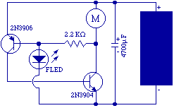
The original FLED-based SE uses a flashing LED to drive a type 1 solar engine (you'll note that it's just like the Zener-based SE, but with a FLED in the starring role). The good news is that all the...
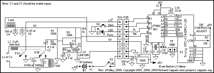
If this picture above looks a lot like the Pretty Good LC Meter also on this web site, that's because it's the same meter, but with some significant improvements. At this point, it's a good idea to read the...

In some cases, a cogwheel input is necessary for voltage measurement. By utilizing a single operational amplifier, an adapter can be created to accommodate a differential input for a ground-referenced voltmeter. It is recommended to use 1% tolerance metal...

The remote control transmitter consists of a DTMF generator and an FM transmitter circuit. A UM91214B phone-specific integrated circuit (IC) is utilized to generate the DTMF signal, with a 3V power supply provided by a 3V zener diode (D1)....

The FIG potentiometer RP2 has a sliding contact that is directly connected to the antenna. The system operates such that only when potentiometers RP1 and RP2 are positioned identically, do the non-conductive transistors and rectifier bridge remain off, resulting...