
Stereo balancer

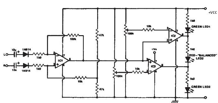
This circuit functions as a stereo balancer, allowing for precise gain matching between two audio channels. It employs a feedback mechanism using resistors R2 to sample the output signal across the load resistors of each channel. The choice of resistor values is crucial; for example, using 2 kΩ resistors for 20 mA LEDs ensures that the circuit operates within safe limits while providing adequate brightness. The adjustment of R3 serves as a fine-tuning mechanism, allowing the user to match the brightness of the two LEDs, which visually indicates the balance between the channels.
In practical applications, the circuit can be integrated into various audio systems, enhancing the listening experience by ensuring that both channels deliver sound at the same level. The setup process is straightforward, requiring only the connection of inputs to the power amplifier and subsequent adjustments to achieve the desired output. When utilized with loudspeakers, the circuit's flexibility allows for easy adaptation by removing the load resistors and directly connecting the speakers, maintaining functionality without compromising audio quality.
Overall, this stereo balancer circuit is an effective solution for achieving equal gain levels in audio applications, making it suitable for both amateur and professional audio setups.This circuit will allow you to set the gain of two stereo channels to the same level. The signal across the two channel-load resistors is sampled by resistors R2. (Values of these resistors will depend upon the power level) For most 20 milliampere LED, use approximately 2 K per watt. (For a 10-watt system use a 25,000 ohm resistor) To set up, short the two inputs and connect them to one channel of a power amplifier.
Apply a signal and adjust R3 until both LEDs glow at the same brightness level The balancer is ready for use. Connect the inputs of the stereo balancer across the output of the power amplifier, and then turn up either the independent volume controls, or the balance control until both LEDs glow at the same level. To use this circuit in-line with loudspeakers, disconnect both Rls, and use the speakers as the load.
Related Circuits
To omit the balance control when using separate potentiometers for the volume controls, refer to the balance control notes on the 7-tube output amplifier page. A schematic was utilized to build a modified version with separate bass and treble...
With this circuit you can mix four separate audio inputs. Each input will accept high or low impedance microphones, phonograph, tape or aux signals. You can adjust the gain of each input by adjusting each respective pot. With the...
This stereo balance indicator circuit diagram is designed using a few common external components. The schematic circuit is very simple to build and will provide a visual indication with LEDs for left, right, and center balance. Outputs from each...
Most cards of sound in computer are deprived stereo input for microphone; on the contrary, they have stereo input for high level (Line). The circuit uses the input Line of the sound card in order to connect two mono...
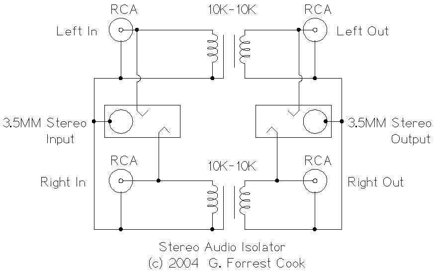
This circuit is useful for removing ground loop hum on a remote line level audio signal line. It can be used to connect a computer sound card to a stereo amplifier's line input. Other uses include tapping into a...
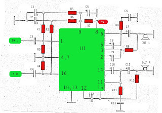
The amplifier circuit utilizes the STK integrated circuit, similar to a previous design. This circuit features two inputs and two outputs, commonly known as a stereo amplifier. It is a power amplifier rated at 2 x 18 Watts with...