
Current-Driven Sallen Key FilterCircuit

The Sallen-Key filter is a widely used active filter topology that employs operational amplifiers (op-amps) to achieve desired filtering characteristics. The current-driven variant of the Sallen-Key filter enhances performance by utilizing a current source instead of a voltage source, which can improve linearity and reduce distortion in audio applications.
In a typical Sallen-Key low-pass filter configuration, two resistors and two capacitors are arranged in a manner that defines the cutoff frequency and the quality factor (Q) of the filter. The op-amp serves as a voltage follower, providing high input impedance and low output impedance, which is essential for maintaining the integrity of the signal being filtered.
The circuit can be described as follows:
1. **Components**: The essential components of the current-driven Sallen-Key filter include two resistors (R1 and R2), two capacitors (C1 and C2), and an operational amplifier (U1). Additionally, a current source (I) is used to drive the input signal.
2. **Configuration**: The first capacitor (C1) is connected to the non-inverting input of the op-amp, while the second capacitor (C2) is connected in feedback from the output to the inverting input. The resistors (R1 and R2) are placed in series with the capacitors to set the filter characteristics.
3. **Transfer Function**: The transfer function of the filter can be derived from the component values and describes how the output signal relates to the input signal across different frequencies. The cutoff frequency (fc) is determined by the formula:
\[
f_c = \frac{1}{2\pi\sqrt{R1 \cdot R2 \cdot C1 \cdot C2}}
\]
This relationship allows designers to choose component values to achieve the desired frequency response.
4. **Applications**: The current-driven Sallen-Key low-pass filter is particularly useful in audio processing, signal conditioning, and data acquisition systems, where clean and precise filtering of signals is critical.
5. **Advantages**: The primary advantages of this filter topology include simplicity in design, ease of implementation, and the ability to achieve high performance with minimal component count. The use of a current source can also offer improved performance characteristics compared to traditional voltage-driven filters.
This Sallen-Key filter design exemplifies a balance between simplicity and functionality, making it a preferred choice in various electronic applications.Current-Driven Sallen Key Filter Circuit Diagram he low-pass Sallen-Key filter is staple for designers because it contains few components (A). By redesigning the filter, 🔗 External reference
Related Circuits
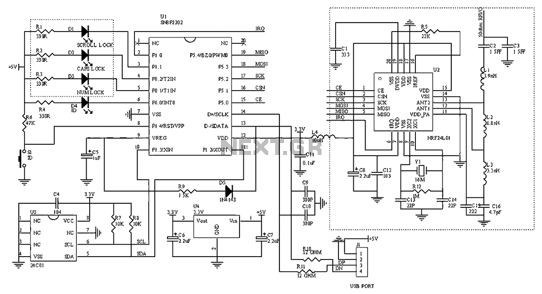
The circuit diagram for the receiving portion of a 2.4 GHz wireless keyboard is presented below. The 2.4 GHz wireless keyboard receiving circuit typically consists of several key components that work together to receive and process signals transmitted from the...
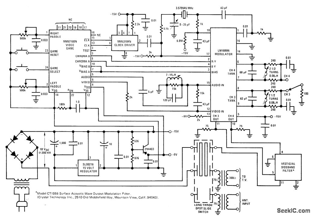
The circuit utilizes the MM57100 TV game chip from National Semiconductor to generate logic for backgrounds, paddles, a ball, and digital scoring. It produces all necessary timing signals, including sync, blanking, and burst, to interface directly with the antenna...

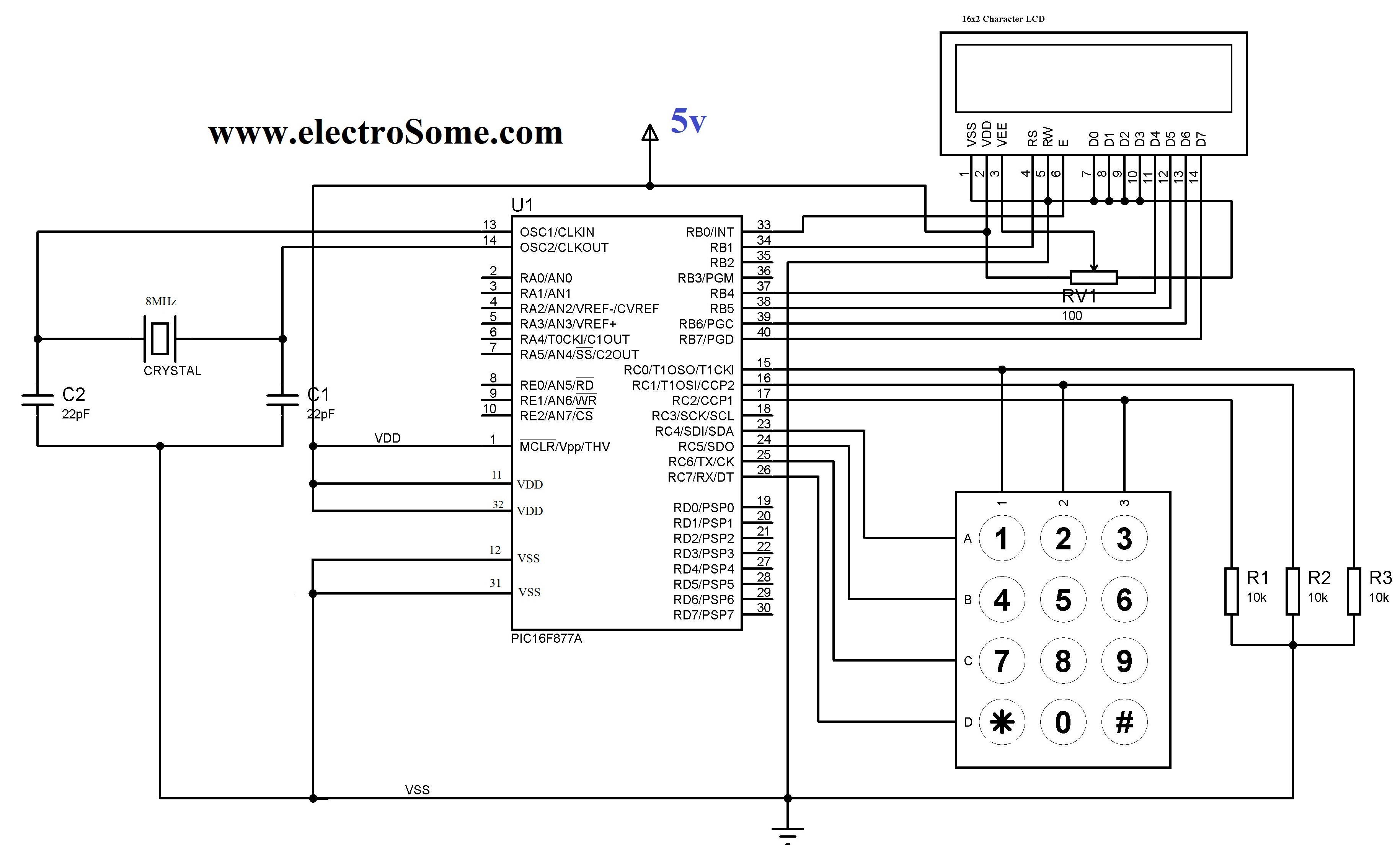
This design circuit functions as an alarm system controlled by a keypad. The core component of the circuit is a single transistor from the BC547 series. The circuit requires a 12-key pad, which has 13 terminals; a matrix type...
This function initializes a specific port for keypad operation. A global variable for the keypad port must be defined before using this function. The port needs to be initialized prior to calling the function. It reads the key when...
This is an enhanced 5 digit keypad which may be used with the Modular Alarm System. The enhanced 5-digit keypad serves as a user interface for the Modular Alarm System, allowing users to input numeric codes for system control. The...
Figure 14-41 illustrates a multivibrator circuit utilizing a 555 timer alongside various capacitive and resistive components. The oscillation frequency is determined by the values of Ra, R16, and C3, following the formula f = 1.44 / ((Ra + 2R16)...