
Stereo Preamplifier and Bass-booster

This preamplifier circuit is engineered to enhance audio signals from various sources, such as CD players and tape recorders, allowing them to effectively drive power amplifiers that may have lower sensitivity. The design incorporates a gain of 4, which is critical for ensuring that the output signal is sufficiently strong for downstream amplification.
A notable feature of this circuit is the bass-boost capability, which addresses the common issue of diminished low-frequency response that arises from using compact loudspeaker systems. The bass-boost can be adjusted using a variable resistor, enabling users to tailor the enhancement from 0 dB to a maximum of +16 dB at 30 Hz. For applications requiring a fixed bass-boost level, the variable resistor can be replaced with a switch, streamlining the circuit configuration.
The schematic provided illustrates the left channel of the preamplifier, with components such as resistors (R1, R2, R3) and capacitors (C1, C2, C3) that are shared between the left and right channels. To achieve stereo functionality, components including potentiometers (P1, P2 or SW1), resistors (R4, R5, R6, R7, R8), and capacitors (C4, C5, C6, C7) must be duplicated.
The circuit's performance is characterized by its total harmonic distortion (THD) values, which are impressively low across various frequencies and output levels. For example, at 1 kHz with a 1 V RMS output, the THD is measured at just 0.006%, indicating high fidelity in audio reproduction. Additionally, the preamplifier can handle significant input voltages, with maximum levels reaching 500 mV RMS at 50 Hz and 700 mV RMS at 100 Hz, ensuring compatibility with a wide range of audio sources.
The current consumption of the circuit is relatively low at 2 mA, making it suitable for integration into battery-powered or low-power audio applications. The circuit design allows for flexibility in operation, particularly with the inclusion of a DPST switch (SW1) for stereo configurations, which can toggle the bass-boost feature on or off, depending on the desired audio output characteristics.This preamplifier was designed to cope with CD players, tuners, tape recorders etc., providing a gain of 4, in order to drive less sensitive power amplifiers. As modern Hi-Fi home equipment is frequently fitted with small loudspeaker cabinets, the bass frequency range is rather sacrificed.
This circuit features also a bass-boost, in order to overcome this problem. You can use a variable resistor to set the bass-boost from 0 to a maximum of +16dB @ 30Hz. If a fixed, maximum boost value is needed, the variable resistor can be omitted and substituted by a switch. Schematic shows left channel only, but R1, R2, R3 and C1, C2, C3 are common to both channels. For stereo operation P1, P2 (or SW1), R4, R5, R6, R7, R8 and C4, C5, C6, C7 must be doubled. Numbers in parentheses show IC1 right channel pin connections. A log type for P2 ensures a more linear regulation of bass-boost. Needing a simple boost-in boost-out operation, P2 must be omitted and SW1 added as shown in the diagram. For stereo operation SW1 must be a DPST type. Please note that, using SW1, the boost is on when the switch is open, and off when the switch is closed.
Technical data (30V supply): Gain @ 1KHz: 4 Max. input voltage @ 50Hz: 500mV RMS (280mV RMS @ 20V supply) Max. input voltage @ 100Hz: 700mV RMS (460mV RMS @ 20V supply) Max. output voltage: >8V RMS (>5V RMS @ 20V supply) Max. bass-boost referred to 1KHz: 400Hz = +2dB; 200Hz = +5dB; 100Hz = +10dB; 50Hz = +14dB; 30Hz = +16dB Total harmonic distortion @ 100Hz and 1V RMS output: 0.02% Total harmonic distortion @ 1KHz and 1V RMS output: 0.006% Total harmonic distortion @10KHz and 1V RMS output: 0.007% Total harmonic distortion @ 100Hz and 5V RMS output: 0.02% Total harmonic distortion @ 1KHz and 5V RMS output: 0.0013% Total harmonic distortion @10KHz and 5V RMS output: 0.005% Current drawing: 2mA 🔗 External reference
Related Circuits
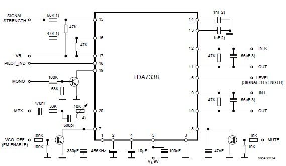
The pilot detector output is configured as an open collector output, necessitating the use of an external pull-up resistor. To set the decoder to "MONO," Pin 19 must be clamped to a voltage lower than 0.8V. The open collector output...
%2B2%2BCH%2Bby%2BIC%2B%2BNE5532%2Bor%2BLF353.jpg)
This is a microphone preamplifier circuit model 2 CH. The circuit utilizes integrated circuits NE5532 or LF353 to amplify the sound signal from a dynamic microphone, increasing the power level for subsequent input into a stereo power amplifier. This...
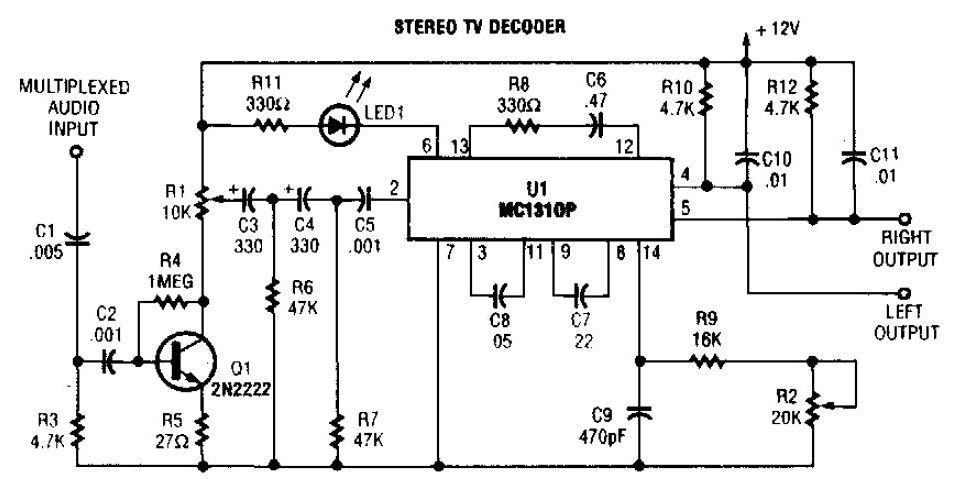
A simple stereo TV decoder circuit built with the MC1310P. Transistor Q1 functions as an audio amplifier, while U1 operates at a 31.5 kHz subcarrier frequency, which is similar to a 38 kHz FM multiplex. The pilot frequency is...
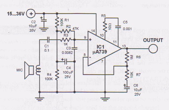
This microphone preamplifier utilizes the low-noise integrated circuit (IC) uA739. The circuit serves as an example of an effective design for preamplifying dynamic microphones. The IC contains two operational amplifiers. The uA739 is a precision integrated circuit known for its...
The circuit is a preamplifier with digital regulation intensity of sound. It is separated into three departments. The first schematic (Fig.1) shows the control circuit of the electronic potentiometer. The control is achieved through two pressing switches. The S1...
This circuit is a low voltage microphone preamplifier that operates with a 1.5V power supply. It features a reference with a 500 kHz unity-gain bandwidth, functioning as a preamplifier with a gain of 100. The output from this stage...