
Stitching Machine Motor Speed Control

The motor speed control circuit for stitching machines is designed to provide precise control over the operation of the motor, allowing for varying stitching speeds based on user input. The system typically includes a foot pedal interface, which incorporates a variable resistor or potentiometer to detect the pressure applied by the operator.
When the foot pedal is pressed, the resistance changes, sending a corresponding voltage signal to the motor controller. This controller interprets the voltage level and adjusts the power supplied to the motor, thereby controlling its speed. The enclosure containing the carbon buttons serves as a protective housing, ensuring durability and reliability in a workshop environment.
Additional components may include a microcontroller for enhanced functionality, enabling features such as programmable speed settings and feedback mechanisms. Safety features such as overcurrent protection and thermal shutdown may also be integrated into the circuit to prevent damage to the motor and associated components.
The overall design emphasizes efficiency and user-friendliness, allowing operators to achieve optimal stitching results with minimal effort. Proper attention to the selection of materials and components is essential to ensure longevity and consistent performance in industrial applications.Stitching Machine Motor Speed Control, Motor operated stitching machines have a series of carbon buttons in an enclosure operated by foot pedal. As the pressure on the foot pedal is increase.. 🔗 External reference
Related Circuits
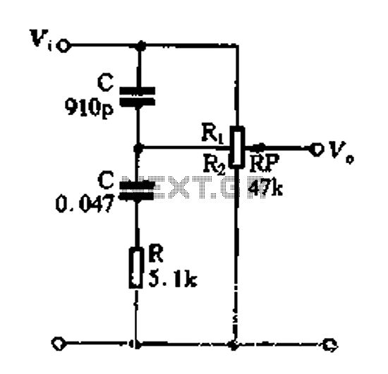
Figure 1-89 illustrates a loudness control circuit. A potentiometer is connected to ground, with 30% of the total resistance at the tap. When the slider arm is adjusted to the tap position, a midrange attenuation of 30 dB is...
A timing and counting circuit utilizing integrated circuit chips with seven-segment LED displays is employed to show the current lap time, previous lap time, and total number of laps completed on a 1/64th-scale slot car racetrack. A switch activated...
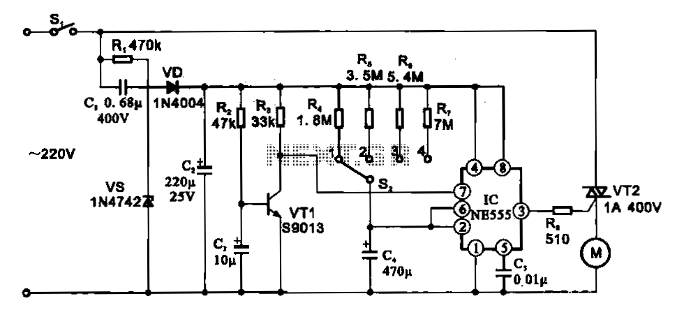
The fan motor driving circuit is depicted as a basic configuration comprising a power circuit and a motor drive circuit. The power supply circuit primarily consists of a power switch (SI), a capacitor (C1), resistors (R1), a Zener diode...
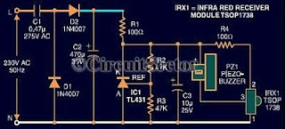
An infrared remote control tester circuit that can be constructed inexpensively. This IR tester is built around an infrared receiver module TSOP1738. The remote control's state can be observed through the sound of a buzzer. The circuit is highly...
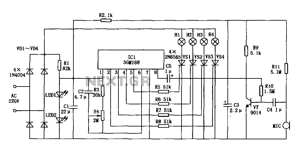
Family karaoke lighting design incorporates various methods for circuit control. The control circuit described here features a four-way light output with loop jumping and speed control capabilities. A microphone detects the acoustic signal strength, allowing the lights to jump...
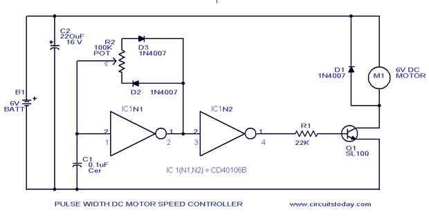
A simple PWM motor speed control circuit with a diagram and schematic for low power DC motors. This easy-to-make PWM DC motor controller is created using the IC CD40106B. The PWM (Pulse Width Modulation) motor speed control circuit utilizes the...