
Street light control circuit

The streetlight control circuit provides a robust solution for automated street lighting management, ensuring efficient energy usage and enhanced safety for pedestrians. Its design incorporates a photosensitive resistor to detect ambient light levels, allowing for automatic switching of streetlights based on natural light conditions. This feature is particularly beneficial in urban environments where lighting needs can vary significantly throughout the day and night.
The integration of the NE555 timer circuit serves as the heart of the control mechanism, enabling precise timing and control functions. The use of a thyristor in the switching circuit allows for effective control of high-power loads, such as street lamps, while the LED provides visual feedback for the operational status of the circuit. The filtering and rectification stages ensure that the power supply to the NE555 is stable and sufficient for reliable operation.
Overall, this streetlight control circuit exemplifies an effective application of electronic components to achieve a practical solution for urban lighting challenges, promoting both efficiency and safety in public spaces.Street wear trench pipe installation commonly used Concealed wiring methods. The control section is installed in the front door or in the centralized control room duty electrician. Street factory area is shown in a FIG. In addition to its convenient transportation, but also the people along the road of leisure, walking, play, exercise areas. Works street light control circuit: street light control is characterized by stable and reliable, and will not cause glare accidental erroneous operation or flashes.
The street light control circuit consists of light control flip-flop circuit, a switching circuit and power supply circuit, as shown in Figure 16-45b. Street light control circuit, the light control flip-flop circuit by the photosensitive resistor RG. Potentiometer RP, capacitor C3,0, resistors R3 and base integrated circuit NE555 composition; switching circuit consists of thyristor VTH, the resistor R2 and the light emitting diode LED composition; power circuit consists of step-down capacitor Ci, resistor R ,, steady pressure diode vS, composed rectifier diode VD and filter capacitor G.
AC 220V step-down voltage by Cl, vs regulator, VD C2 rectified and filtered to produce 8. SV (V0) DC voltage supply NE555. During the day, photoresistor RG affected by light exposure to the low resistance state, feet and feet higher than the potential of NE555 2V.T / 3, NE555 the pin output low, LED does not light-emitting diode, thyristor VTH is off state, EL lamp does not light. When night falls, the light intensity gradually weakened, photosensitive resistor RG resistance increases.
pin voltage NE555 feet and have begun to decline, when the voltage drops below the feet V "/ 3 ±, NE555 internal flip . feet from low to high, the LED is turned on hair light. VTH triggered by conduction, the EL lamp is lit.
Related Circuits
This oscillator is a variation of the oscillator presented by Ulrich L. Rohde, DJ2LR, in his article "Evaluating Noise Sideband Performance in Oscillators," published in Ham Radio, October 1978, Page 51. The original circuit can be found at the...
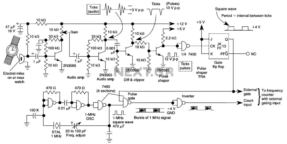
This circuit adapts a frequency counter to measure intervals. It was originally utilized as a shutter speed checker for photographic applications. The watch ticks are clipped, shaped, and formed into a square wave. This square wave is employed to...
With this circuit we can create a altered sound of siren. The oscillator IC1a-b is constituted by two gates NAND, oscillating in very low frequency. This oscillation drive the IC2, that is a electronic switch, which opens and closes...
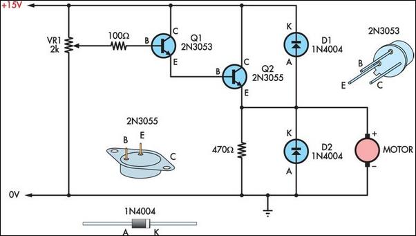
Two simple 12V DC motor speed controllers can be constructed for a minimal cost. These controllers take advantage of the principle that the rotational speed of a DC motor... DC motor speed controllers are essential components in various applications where...

Today, it is no longer necessary to use discrete components for constructing oscillators. Many manufacturers now offer ready-made voltage-controlled oscillator (VCO) integrated circuits (ICs) that require only a few external components to determine the frequency. An example of such...

The WS2512-TR1G is a Wide-band Code Division Multiple Access (WCDMA) Power Amplifier (PA) designed as a fully matched 10-pin surface mount module, specifically developed for WCDMA handset applications. This power amplifier module operates within a frequency range of 1920-1980...