
Two Basic Motor Speed Controllers

DC motor speed controllers are essential components in various applications where precise control of motor speed is required. The two designs mentioned utilize different methods to achieve speed control, which can be beneficial depending on the specific requirements of the application.
The first design employs a Pulse Width Modulation (PWM) technique. In this configuration, a microcontroller generates a PWM signal that modulates the average voltage supplied to the motor. By adjusting the duty cycle of the PWM signal, the effective voltage can be varied, resulting in a change in the motor's speed. This method is highly efficient, as it minimizes power loss and generates less heat compared to other control methods. The circuit typically includes a MOSFET or transistor to handle the current, along with a diode for flyback protection, ensuring that the motor operates smoothly without damaging the components.
The second design utilizes a simple resistive control method. This approach involves placing a variable resistor or potentiometer in series with the motor. By adjusting the resistance, the voltage drop across the motor changes, thereby altering its speed. While this method is straightforward and inexpensive, it is less efficient than PWM control, as it dissipates power as heat in the resistor, which can lead to overheating and reduced lifespan of the components.
Both designs can be implemented with minimal components, making them cost-effective solutions for controlling 12V DC motors. Careful consideration should be given to the choice of components, such as the rating of the MOSFET or resistor, to ensure they can handle the motor's current without overheating. Additionally, incorporating safety features like fuses or thermal cutoffs can enhance the reliability and longevity of the motor speed controllers.Here are two simple 12V DC motor speed controllers that can be built for just a few dollars. They exploit the fact that the rotational speed of a DC motor.. 🔗 External reference
Related Circuits
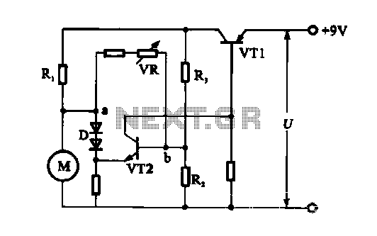
The electronic circuit for steady speed motor applications utilizes an automatic remote control system to regulate the motor power supply, thereby achieving consistent speed control. The circuit diagram illustrates a DC motor connected to the system. Given that the...
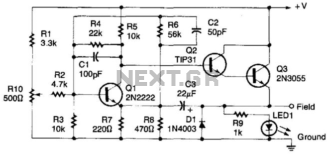
This regulator circuit can be used on an alternator that has one field terminal grounded. When the input voltage becomes too high, Q1 conducts, and the base of Q2 is driven toward ground, reducing the voltage fed to Q3....
The TBA120U is an intermediate frequency (IF) amplifier that includes a symmetrical frequency modulation (FM) demodulator and an audio frequency (AF) amplifier with adjustable output voltage. The AF amplifier features an output for volume control and an input for...

This is a simple power supply that provides a reliable and clear regulated output voltage ranging from 0 to 28 volts with a maximum current of 6 to 8 amperes. Utilizing two 2N3055 transistors allows for doubling the output...
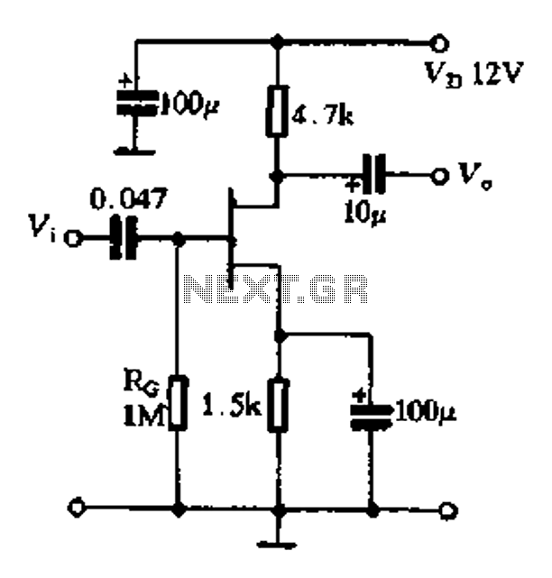
The FET exhibits a high input impedance, a low noise figure, anti-crosstalk capabilities, and good mutual interference performance, making it increasingly utilized in electronic circuits. FET amplifiers can be configured in various ways, including as common source (equivalent to...
This circuit includes an intermittent siren output with automatic reset functionality. It can be activated manually via a key switch or a concealed switch, or it can be configured to activate automatically when the ignition is turned off. By...