
Strobe Alarm

The described circuit is a strobe light system that visually indicates sensor input activity. The light-dependent resistor (LDR) serves as the primary sensor element, responding to changes in light levels. When the input signal is detected, the LDR alters its resistance, influencing the charging dynamics of capacitors C1 and C3. Resistor R4 plays a crucial role in this circuit by controlling the charge time of these capacitors, ensuring that the system responds appropriately to input signals.
Upon activation of the input signal, the circuit initiates a sequence where the neon bulb (NE1) fires, indicating that the voltage across it has reached a threshold. This firing event leads to the rapid discharge of capacitor C3 into the silicon-controlled rectifier (SCR1). The SCR acts as a switch that allows current to flow once it is triggered, thus energizing the circuit and allowing capacitor C2 to discharge through the trigger transformer (T1).
The role of the trigger transformer is significant; it steps up the voltage to a level sufficient to ignite the Flashlamp (FL1). The flashlamp then emits a bright flash of light, providing the visual indication intended by the circuit design. To ensure reliable operation, the power supply for this circuit is specified to provide a high voltage of 330 V, accompanied by a capacitance of 50 to 100 µF. This output capacitance is essential for stabilizing the voltage and ensuring that the flashlamp receives sufficient energy for operation.
Inductor L1, with its 25 mH inductance, is integrated into the circuit to manage the energy discharge rate. This inductance helps to prolong the flash duration, enhancing the visual effect while also contributing to the overall longevity of the flashlamp. The design considerations surrounding component values, such as the capacitance and inductance, are critical for achieving the desired performance characteristics of the strobe system, ensuring that it functions reliably in response to sensor inputs. This strobe gives a visual indication of a sensor input. The input signal causes Ul, a light dependent resistor, to chaijge CI and C3 through R4. When NE1 fires, C3 discharges into SCR1, which triggers it and causes C2 to discharge through trigger transformer Tl, which triggers Flashlamp FL1, The 330-V supply should have about 50 to 100 /iF output capacitance. Ll supplies about 25-mH inductance to prolong the flash and the life of FL1.
Related Circuits
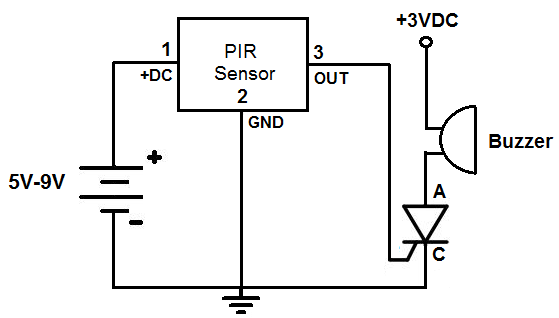
This is an alarm circuit that activates when motion is detected. Upon detection, the circuit triggers an alarm buzzer, which remains activated until the power is disconnected. This type of alarm circuit is commonly used to monitor areas for...
A circuit that offers visual indication of fluid level in a vessel, with a switchable audible alarm. Example uses would be to monitor the level of water in a bath or cold storage tank. Conductance is the reciprocal of...

The thermistor utilized has a resistance of 15k ohms at 25 degrees Celsius and 45k ohms at 0 degrees Celsius. A suitable bead-type thermistor can be sourced from the Maplin catalogue. The inclusion of a 100k potentiometer enables this...
When the resistance value of temperature, light, pressure, or any other resistive sensors (Rs) drops below a certain threshold, which can be adjusted by a preset. In electronic circuits, resistive sensors such as thermistors, photoresistors, and piezoresistors are commonly used...

This is an enhanced 5 digit keypad which may be used with the Modular Alarm System. The enhanced 5-digit keypad serves as a user interface for the Modular Alarm System, allowing users to input numeric codes for system control. The...
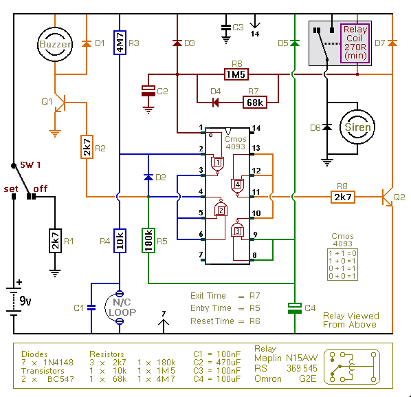
This is an improved version of the basic Garage/Shed Alarm. The Entry and Exit delays have been extended to approximately 30 seconds, and a timed Siren cut-off along with an automatic reset feature has been added. Additionally, the LED...