Enhanced 5 Digit Alarm Keypad
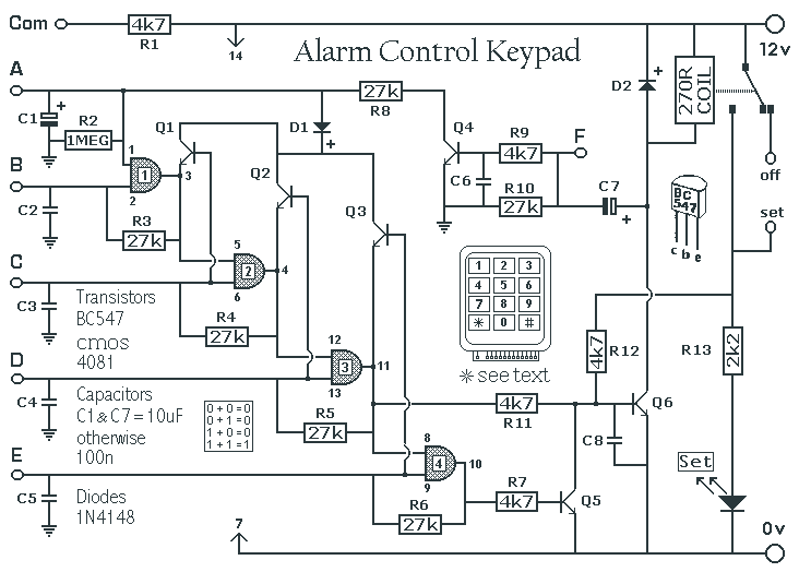
This is an enhanced 5 digit keypad which may be used with the Modular Alarm System.
The enhanced 5-digit keypad serves as a user interface for the Modular Alarm System, allowing users to input numeric codes for system control. The keypad typically consists of a matrix of buttons arranged in a 3x4 grid, enabling the entry of digits 0 through 9, along with additional function keys such as 'Enter' and 'Clear'.
The keypad operates using a microcontroller that scans the button presses and translates them into corresponding digital signals. Each key press is detected through a combination of row and column scanning. When a key is pressed, it connects a specific row to a column, allowing the microcontroller to identify which key has been activated.
To enhance security, the keypad may incorporate features such as backlighting, tamper detection, and a built-in buzzer for feedback on key presses. The device can be connected to the alarm system via a dedicated communication protocol, typically using a serial or parallel interface, ensuring reliable data transmission.
Power supply requirements for the keypad are generally modest, often operating at 5V DC, which can be supplied from the alarm system's main power source. Additionally, the keypad may include debounce circuitry to prevent false triggering due to mechanical bounce when a key is pressed.
Overall, the enhanced 5-digit keypad is a critical component of the Modular Alarm System, providing a user-friendly interface while maintaining robust security features.This is an enhanced 5 digit keypad which may be used with the Modular Alarm System. 🔗 External reference
