
Structure and working principle of brushless motor windings

The brushless motor operates on the principle of electromagnetic induction, where the interaction between the stator's rotating magnetic field and the rotor's magnetic field generates motion. The triangular coils are arranged in a specific configuration to optimize the magnetic field's efficiency and performance.
In a brushless motor, the stator consists of multiple windings, often arranged in a triangular pattern, which allows for effective magnetic field generation. The switching mechanism, usually implemented through a series of transistors, controls the timing and sequence of current flow through these windings. This control is crucial, as it determines the direction and speed of the rotor's rotation.
A drive control circuit is essential for managing the switching of the transistors. This circuit typically includes a microcontroller or dedicated driver IC that interprets input signals (such as speed commands) and generates the appropriate control signals to the transistors. The design of the control circuit must ensure that the transitions between different states are smooth and efficient, minimizing losses and maximizing performance.
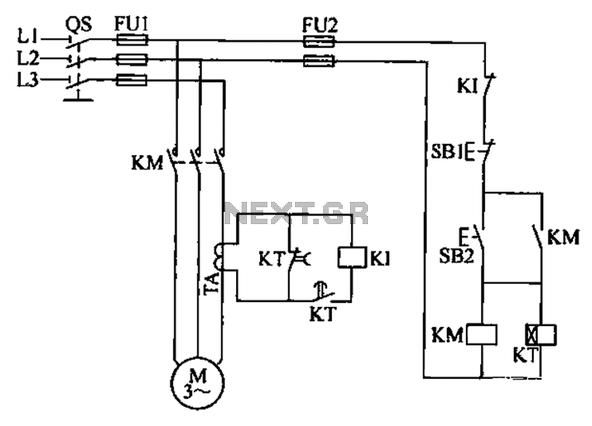
The triangular coil design not only enhances the motor's efficiency but also contributes to its compact size, making brushless motors suitable for a wide range of applications, from small electronic devices to large industrial machinery. The absence of brushes in these motors reduces maintenance needs and increases reliability, further solidifying their preference in modern engineering solutions.Structure and working principle c brushless motor windings Structure and working principle of the triangular coils As shown, through the switch, you can make the stator coil current cycle turned, and the formation of a rotating magnetic field. Can be seen from the figure, the cycle of the week and the current state of the switch path. Is usually caused by switching of the switching transistor, the switch in order to achieve an orderly transition must have a drive control circuit. i class = "else" IC inventory | Part Search | Gallery | Community | 21IC official microblogging |
Related Circuits
This page focuses on radios marketed in the USA, compiled by residents familiar with these products. Contributions regarding non-USA radios are welcome, and a region-specific page could be created. The MaxTrac, Radius, and GM300 series have inspired additional radio...
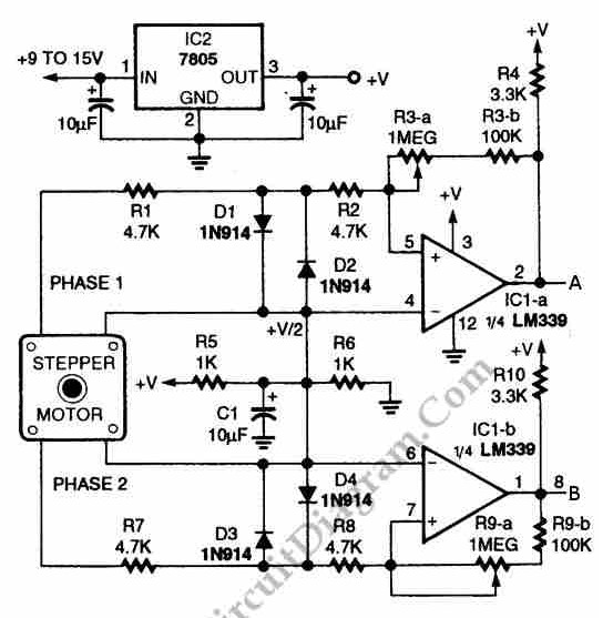
The circuit illustrated in the schematic diagram below allows for the visualization of the direction and shaft rotation of a stepper motor on an LED display. Instead of utilizing a digital rotation encoder as an input, this circuit employs...
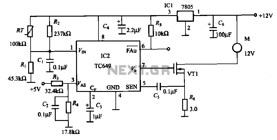
A motor is a heating device that can overheat, often due to accidents or overloads caused by excessive coil winding temperatures. The TC649 motor overheating protection and drive circuit, depicted in FIG. 1-9, utilizes an NTC thermistor (RT) positioned...
This design is intended as a dimmer for a 12V reading lamp, but it can also function as a motor speed controller for devices like drills. The circuit modulates the voltage supplied to the load, allowing for variable pulse...
A three-phase electric motor overcurrent protection circuit. This example circuit utilizes a transformer to monitor the current, ensuring that the currents in the three-phase motor do not exceed normal operating levels. When the current exceeds the set threshold, the...
M1 is a stepper motor salvaged from an old disk drive. It features five pins: common, coil 1, coil 2, coil 3, and coil 4. The resistance measured between the common pin and each coil is approximately 75 Ohms....