
Digital Encoder Circuit diagram Using Stepper Motor

The described circuit integrates a stepper motor with an LED display to provide real-time feedback on the motor's rotational direction and position. The stepper motor operates through a series of discrete steps, allowing for precise control of its rotation. In this configuration, the motor's rotation is monitored by a microcontroller, which interprets the signals from the motor and translates them into visual information displayed on the LED screen.
The schematic typically includes the stepper motor, a microcontroller (such as an Arduino or similar device), and the LED display. The microcontroller is programmed to control the stepper motor's operation, sending pulse signals to the motor driver, which in turn energizes the motor coils in a specific sequence. This sequential energization causes the motor to rotate in defined steps, either clockwise or counterclockwise.
The LED display is interfaced with the microcontroller to show the current position of the motor shaft. The display can represent the rotation direction with indicators such as arrows or numerical values indicating degrees of rotation. The circuit may also include additional components such as resistors, capacitors, and possibly a power supply to ensure stable operation.
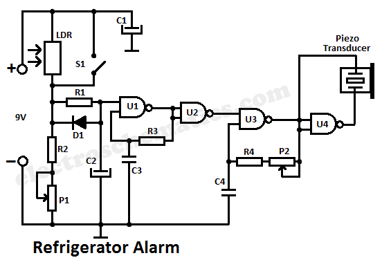
In summary, this circuit is an effective solution for applications requiring precise motor control and visual feedback, allowing users to monitor and adjust the motor's performance in real-time. The schematic diagram serves as a crucial reference for understanding the connections and components involved in the setup.Using circuit depicted in the schematic diagram below, the direction and shaft rotation of stepper motor can be seen on the LED display. Alternative to digital rotation encoder as a digital encoder input, this circuit uses a stepper motor.
Here is the schematic diagram of the circuit:.. 🔗 External reference
Related Circuits
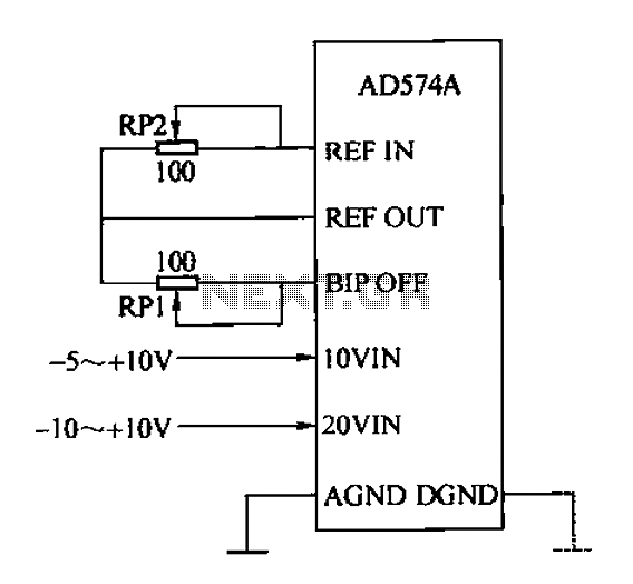
The AD574A is a high-performance 12-bit successive approximation analog-to-digital (A/D) converter that can interface directly with an 8 or 16-bit microprocessor bus. The input to the AD574A can be either unipolar or bipolar. The unipolar analog input voltage range...
The digital delay presented here is expected to be sufficient for most applications, and although the delay is fixed at 20ms, this is the most usable delay period. This is the equivalent of being about 7 metres away from...
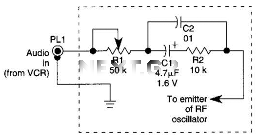
This continuous wave (CW) transmitter is capable of producing an output power of up to 3 watts. By applying a 24-volt supply to transistor Q2, the output power can be increased to as much as 10 watts. It is...
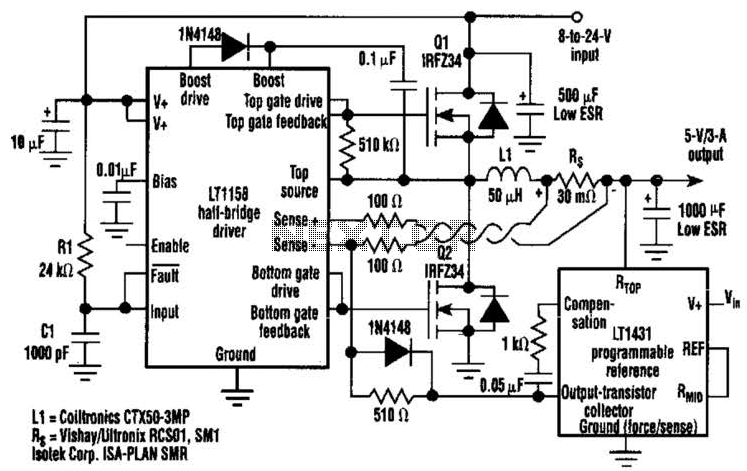
This regulator achieves 90% efficiency with a 12-V input and a 5-V output. It utilizes the LT1158 and LT1431 components from Linear Technology, Inc. High efficiency is accomplished by synchronously switching two power MOSFETs in a step-down switching regulator....
A simple light fence security beeper is presented. This circuit can function as a door alarm, gate alarm, pathway alarm, etc. It can be powered by any 12 Volt DC power supply. The operation of this circuit is straightforward....
Telephones are declining globally; however, India has over 350 million mobile phone users, alongside a significant number of traditional telephone users. This telephone timer is designed to save costs by controlling unnecessary time spent during phone calls. This simple...