
studio ring flash xenon tubes

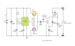
The MOC3020M is an optoisolator designed for interfacing low-voltage control circuits with high-voltage loads, making it suitable for applications where electrical isolation is required. To implement an LED indicator for capacitor charging, a simple circuit can be designed using the MOC3020M along with the 5V LEDs.
The circuit will consist of the following components:
1. **Capacitor**: This is the component whose charging status will be monitored. Select capacitors based on the required capacitance and voltage ratings for the application.
2. **MOC3020M**: This optoisolator will be employed to provide electrical isolation. The input side will be connected to the capacitor, while the output side will drive the LED.
3. **LED**: A 5V LED will be used as an indicator. It should be connected in series with a current-limiting resistor to prevent excessive current from damaging the LED.
4. **Resistor**: A resistor will be placed in series with the LED to limit the current flowing through it. The value of this resistor can be calculated using Ohm’s law, considering the LED's forward voltage and the supply voltage.
5. **Power Supply**: A 5V power supply will be used to power the LED and the MOC3020M.
The circuit operation will be as follows: When the capacitor is charging, the voltage across it will rise. Once it reaches a certain threshold, the MOC3020M will activate, allowing current to flow through the LED, thus illuminating it. This visual feedback will indicate that the capacitor is charged.
To ensure proper functionality, it is crucial to select the correct threshold voltage for the MOC3020M and to verify that the LED is rated for the intended current. Additionally, testing the circuit with a multimeter before connecting the LED can help prevent any potential damage during the live test.
This setup provides a straightforward method to visually indicate the charging status of capacitors while leveraging the existing components effectively.MOC3020M Integrated Circuit. I would love a LED to tell me when each cap is charged but I have no idea how to do that or where to put in the circuit, I have a bucket load of 5v LEDs so making use of some would be great. I have Circuit maker but dont have a spice for a xenon and cant find one anywhere so cant virtually test this circuit so its going to be a live test so I dont want to cook it.
🔗 External reference
Related Circuits
A telephone ringer capable of making any mains-powered device operate from the ringer of a fixed line telephone. This device allows the control of a high-powered siren or horn to amplify the low-level sound of a telephone, making it...
This telephone ringer utilizes an AMI chip with part number S2561 and can be powered directly from the telephone line. The audio output is approximately 50 mW when supplied with a 10-V source. The circuit design of the telephone ringer...
This is a simple and cost-effective inverter designed to power a small soldering iron (25W, 35W, etc.) in situations where a mains supply is unavailable. The circuit utilizes eight transistors. The inverter circuit operates by converting DC voltage from a...
This bat detector circuit was created by Chris Eve. Initial tests with various salvaged electret microphones demonstrated a good response to frequencies of 50 kHz and higher, with smaller units performing better. Tests indicate that a small electret microphone,...
The Slave Flash Trigger is activated by pressing a push button. When activated, the indicator lamp emits one to three flickers to indicate the programmed mode. One flicker means the flash will fire with each flash, two flickers indicate...
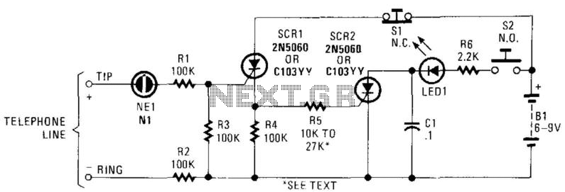
In this circuit, the ringing voltage on a telephone line causes NE-1 to break over, triggering SCR1, which in turn triggers SCR2. If a call has been received, depressing S2 will cause LED1 to light. Depressing S1 resets the...