
Telephone Visual Ring Indicator

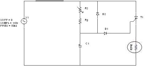
The described circuit utilizes a combination of a neon bulb (NE-1), silicon-controlled rectifiers (SCR1 and SCR2), and a couple of switches (S1 and S2) to efficiently indicate incoming calls with minimal power consumption. The operation begins when the telephone line experiences a ringing voltage, which causes NE-1 to ionize and conduct. This action activates SCR1, allowing current to flow to SCR2, which may be used to drive additional components or indicators.
When a call is received, the user can press switch S2, which activates LED1, providing a visual indication of the incoming call. This design choice ensures that LED1 only illuminates when S2 is pressed, thereby conserving battery power. The circuit is designed to reset when switch S1 is pressed, cutting off the current and returning the system to its idle state. This method of operation not only extends battery life but also enhances the reliability of the circuit by preventing continuous LED illumination, which could otherwise lead to unnecessary power drain.
The overall schematic will typically include the telephone line input, the NE-1 connected in parallel with a resistor to limit current, SCR1 and SCR2 configured in a manner that allows for the triggering mechanism, and the switches S1 and S2 arranged to facilitate user interaction with the circuit. The design emphasizes simplicity and efficiency, making it suitable for applications where power conservation is critical. In this circuit, the ringing voltage on a telephone line causes NE-1 to break over, triggering SCR1, which in turn triggers SCR2. If a call has been received, depressing S2 will cause LED1 to light. Depressing SI resets the circuit. This circuit has the advantage of lower battery drain because LED1 is not left on continuously after a ring signal, but only when S2 is depressed.
Related Circuits

The circuit operates by sending ringing pulses through capacitor C1, resistor R1, and diode D2 to charge capacitor C2 to a voltage of 6V. This voltage causes transistors N1 and N2 to reverse, which activates V1, the analog hook,...
The diagram illustrates an R-C-Diode circuit that provides full half-cycle control (180 electrical degrees). During the positive half-cycle of the SCR anode voltage, the capacitor charges to the trigger point of the SCR, a process governed by the RC...
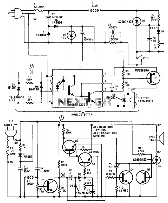
This device comprises a ring detector connected to the telephone line. When the telephone rings, the ring detector imposes high-frequency pulses on the AC power line. A receiver located anywhere on the same power line detects these pulses and produces...
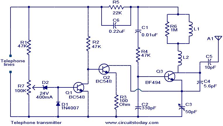
This circuit is a simple yet effective design for transmitting telephone conversations. When the telephone receiver is on-hook, the voltage across the lines is approximately 48 volts. The preset resistor R7 is adjusted to achieve a voltage of 24.7...
The output current of the control circuit must be amplified when the gate current needed to trigger the device exceeds the output current of the control circuit. To achieve the amplification of the control circuit output current, a suitable transistor...
Have you ever been using the modem or fax and someone else picks up the phone, breaking the connection? Well, this simple circuit should put an end to that. It signals that the phone is in use by lighting...