
Subwoofer Equaliser

The Linkwitz transform circuit is a sophisticated electronic design that enables the extension of a loudspeaker's frequency response down to 20 Hz or lower. This is particularly useful for subwoofer applications where deep bass reproduction is desired. The circuit effectively modifies the input signal to compensate for the natural roll-off of the loudspeaker's frequency response, allowing it to produce lower frequencies with greater efficiency. The testing procedure described involves placing the speaker in a sealed enclosure and driving it with a significant power level (50 to 100W) at 20 Hz. Observing substantial cone movement without audible tone indicates proper operation, while the presence of a 60 Hz signal suggests harmonic distortion and potential inadequacies in the speaker's performance.
The mixer circuit referenced in the input data is designed to combine multiple audio signals while maintaining isolation between channels. This is crucial in preventing crosstalk and ensuring that each audio source can be processed independently. The mixer employs a virtual earth configuration at the summing point, allowing for the integration of inputs without affecting the integrity of the individual signals. This design choice enhances the overall performance of the audio system, particularly in complex setups where multiple sources are present. The schematic for the mixer circuit (Figure 1) can be integrated into the overall design (Figure 2), providing a seamless interface for audio mixing and processing.The Linkwitz transform circuit (or EAS principle) will allow any driver to extend to 20 Hz or even lower. A good quick test is to stick the speaker in a box, and drive it to 50 or 100W or so at 20 Hz - you should see a lot of cone movement, a few things will rattle, but you shouldn`t actually hear a tone.
A "bad" speaker will generate 60 Hz (third harmonic) - if you don`t hear anything, the speaker will work in an equalised sub. A simple mixer circuit is shown in Figure 1, and this is simply be added to the front end of the circuit in Figure 2. The mixer stage completely isolates each channel from the other, since the summing point is a "virtual earth" because of the f
🔗 External reference
Related Circuits
The subwoofer is a speaker designed to reproduce low frequencies, specifically in the range of 20 Hz to 150 Hz. The electronic circuit diagram below illustrates the details of a subwoofer amplifier using the TDA1516, a 22-watt amplifier suitable...
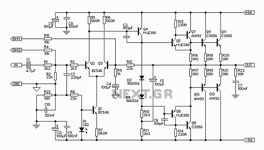
The 300W amplifier circuit presented is a conventional design. It includes connections for the internal SIM and incorporates filtering for RF protection (R1, C2). The input is facilitated through a 4.7µF bipolar capacitor, which offers substantial capacitance in a...

This simple subwoofer circuit is designed to connect to an existing car stereo amplifier, providing the additional "punch" often required for music by driving a subwoofer. Since very low frequencies are omnidirectional, a single amplifier is necessary to drive...
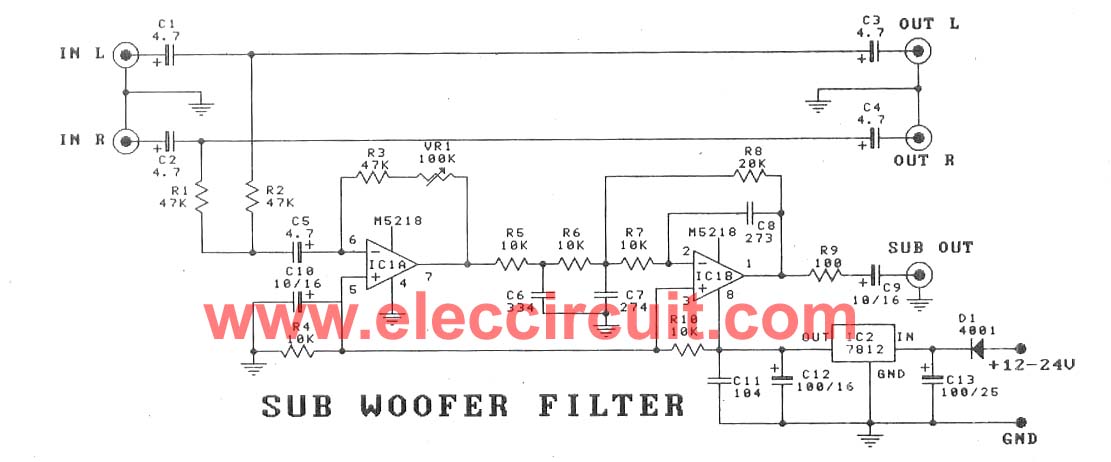
This subwoofer filter set is suitable for use with a high-quality car audio system. The circuit is designed to operate with a 12-volt DC power supply. The subwoofer filter set serves as an essential component in enhancing the audio experience...
In the form it appears the theoretical circuit of filter. In first glance we see three different circuits that are mainly manufactured round two operational amplifiers. This circuits constitute mixed, amplifier with variable aid and a variable filter. The...
The amplifier circuit is well-suited for use in subwoofer speakers due to its robust performance. This circuit utilizes an integrated circuit (IC) based on the STK series. It can be employed in vehicles equipped with speakers or a subwoofer...