
22 Watts Mini Subwoofer Circuit TDA1516 with Adjustable Frequency

The TDA1516 amplifier circuit is designed for optimal performance in automotive applications, where space and efficiency are critical. The BTL configuration allows for higher power output without requiring a transformer, making it a cost-effective solution for driving subwoofers. The use of dual-linear motion potentiometers enables precise control over the volume and frequency response of the subwoofer, allowing the user to tailor the audio experience to their preference.
The inclusion of the dual BIFET Op-Amp enhances the overall audio fidelity by providing low noise and high input impedance, which is essential for maintaining signal integrity. The RCA audio input ensures compatibility with standard car audio systems, allowing for straightforward installation and integration.
The isobaric configuration of the woofers improves efficiency and reduces the required enclosure size, making it an ideal choice for compact automotive environments. The low-pass filter designed with IC1B effectively attenuates frequencies above the desired cutoff point, ensuring that only low frequencies reach the subwoofer, which is crucial for preventing distortion and enhancing the listening experience.
The voltage stabilizer formed by Q1, Q2, R17, and C9 plays a vital role in maintaining consistent performance by filtering out any voltage fluctuations that could adversely affect the amplifier's operation. This careful consideration of component selection and circuit design results in a robust and reliable subwoofer amplifier suitable for various automotive audio applications.The subwoofer is a subwoofer or a speaker to reproduce low frequencies, devotee of 20 Hz to 150 Hz electronic circuit diagram below shows the details of a scheme of the main amplifier TDA1516 22 watt in 4 ohm car subwoofer driver. This device is designed for an existing stereo amplifier, often requires adding another blow to the music of driving a
subwoofer. The amplifier uses BTL is a good and cheap (Bridge Tied Load channels) 13-pin IC TDA1516 from Philips is now NXP Semiconductors), which may provide a small number of components and 22W at 4 ohm load voltage 12 volt car battery default. The device consists of several parts: the name of the potentiometer, dual-linear motion potentiometers, 1/4W resistors, capacitors, electrolytic 25V, 63V Polyester capacitors, LED, 100 mA NPN transistor, dual BIFET Op-Amp, 24 W BTL car radio RCA audio input amplifier and two speakers 4 ohm or 8 ohm woofers in isobaric parallel wiring.
The signals from the line outputs for stereo mixing amplifier input drive, and taking into account the level of the signal to the buffer and can be reversed IC1A phase SW1. Such control may be useful to the subwoofer in phase with the speaker of the existing car radio. Then, a variable frequency 12dB/octave-pass low IC1B, the components of the Q1 and then you can pass the low frequency of 70 Hz or 150 Q2, R17 and C9 form a voltage stabilizer to facilitate access and filtering circuit to prevent track of the services given power at a low level positive.
🔗 External reference
Related Circuits
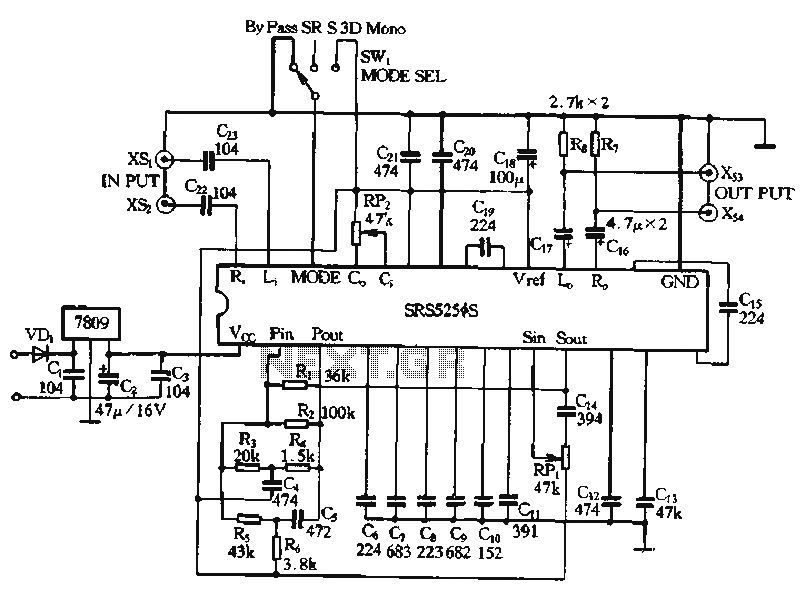
Typical application circuits for the Zheng brick SRS5250S are illustrated in the provided diagram. The SRS5250S features a pin diagram and a processing circuit that allows the user to switch between three operating modes: straight, SRS, and single-channel analog...
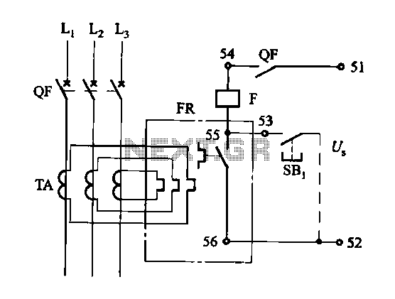
The DK-5A, 5D, and SDb control boxes are equipped with a thermal electromagnetic overcurrent release, as depicted in Figure 6-80. The trip mechanism provides both overload and instantaneous short circuit protection with a long delay feature. In the figure,...
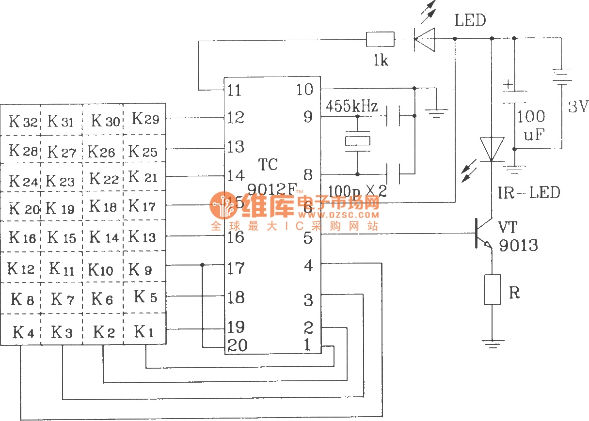
The TC9012 is a specialized off-screen remote control code transmitter. It incorporates an oscillator, divider timing generator, system code latch, data storage, key scan input, key scan output, and carrier control and output units. The internal 8-bit system code...

This is a UHF band TV antenna preamplifier circuit with a gain of 15 dB, built using a BF180 UHF transistor. The circuit is straightforward in design. The operational principle consists of two stages. The first stage features a...
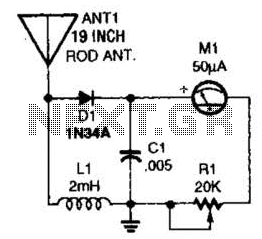
This basic field-strength meter offers an affordable solution for monitoring an amateur radio or CB transmitter, as well as an antenna system, to ensure maximum output. The field-strength meter is designed to measure the strength of radio frequency (RF) signals...
Siren Circuit. This circuit generates a sound siren when switch S1 is pressed, increasing the sound frequency as capacitor C1 charges. The sound frequency decreases when switch S1 is released. The siren circuit operates based on the charging and discharging...