
Subwoofer filter

The circuit employs a series of operational amplifiers to create an effective audio processing system tailored for subwoofer applications. The use of op-amp U1 as a buffer ensures that the input audio signal maintains its integrity without loading the source, allowing for accurate signal transmission to the subsequent high-pass filter stages. This is critical in preserving the quality of the audio signal, particularly for the left channel.
The high-pass filter configuration formed by op-amps U2 and U3 is designed to eliminate frequencies below the desired cutoff, effectively allowing only those above a certain threshold to pass through. This is particularly useful in subwoofer applications where low-frequency signals need to be filtered out to prevent distortion and to optimize the performance of the subwoofer.
For the right channel, the same buffering and filtering principles apply, with op-amp U8 serving as a buffer for the right channel audio source. The high-pass filter created by op-amps U9 and U10 mirrors the design of the left channel filter, ensuring that the right channel audio signal is also appropriately processed.
The mixing of the left and right channel signals occurs at op-amp U4, which combines the outputs from U1 and U8, enabling a coherent stereo output for the subwoofer. The subsequent low-pass filter, constructed from op-amps U5 and U6, is crucial for allowing only the low-frequency components of the mixed signal to pass through, effectively defining the subwoofer's operating range.
The gain adjustment feature implemented through potentiometer R22 connected to op-amp U7 allows for fine-tuning of the output level, providing flexibility to match the subwoofer output with other components in the audio system. This capability is essential for achieving optimal sound levels and integration within a larger audio setup.
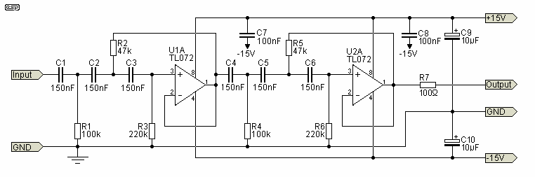
In summary, this op-amp based subwoofer filter circuit provides a comprehensive solution for processing audio signals intended for low-frequency reproduction, ensuring high fidelity and performance in subwoofer applications while allowing for adjustments and modifications based on component availability.Here is the circuit diagram of an opamp based subwoofer filter. Audio frequencies below 200Hz are considered to be in the subwoofer range. So a subwoofer filter will be essentially a low pass filter with a cut off frequency of 200Hz. The working of this straight forward circuit is as follows. The left channel of the audio source is connected to the non-inverting input of opamp U1 which is wired as a buffer. Opamps U2 and U3 forms a high pass filter. Output of U1 is coupled the input of this high pass filter. The high pass filtered audio signal available at the output of U3 represents left channel output. Similarly the right channel of the audio source is connected to the non-inverting input of U8 which wired as a buffer amplifier. The output of U8 is connected to the input of the high pass filter formed by opamps U9 and U10. The filtered audio signal available at the output of U10 represents the right channel audio output. Output of U1 and U8 are coupled to the inverting input of the opamp U4. U4 performs the job of mixing the two signals. Output of U4 is coupled to the input of the low pass filter comprising of opamps U5 and U6. The low pass filter has a cut off frequency of 200Hz. The output of the filter is coupled to the inverting input of opamp U7 through the POT R22. U7 works as an output amplifier and POT R22 can be used for adjusting the gain. The audio signal available at the output of U7 represents the subwoofer output. Some capacitance values shown in the circuit are hard to find in the market. The best solution is to combine available capacitors serially or parallely to obtain the required value.
🔗 External reference
Related Circuits
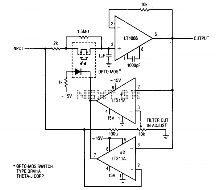
This circuit is useful where fast signal acquisition and high precision are required, such as in electronic scales. The filter's time constant is determined by the 2-ohm resistor and the 1 µF capacitor until comparator No. 1 activates. After...
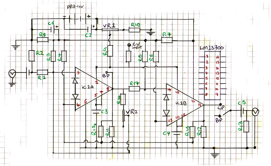
This is a 9V DC powered LM13700 dual transconductance operational amplifier-based filter, highly suitable for battery-powered circuits. The design is adapted from an article by R. A. Penfold for Maplin magazine, incorporating manual filter cut-off and resonance control. At...
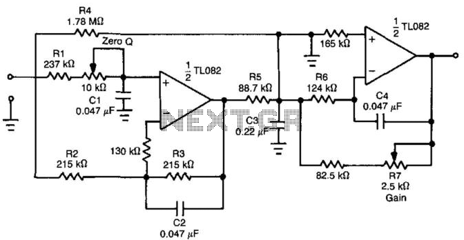
The circuit shown is completely conventional. The Q of the filters has been optimized to allow a higher input impedance than would otherwise be possible, with the final Q of the two filters being almost exactly 0.707 (i.e., a...
By introducing an additional transmission zero to the stopband of a low-pass filter, a sharper roll-off characteristic can be achieved. The filter design example illustrated in Figure 30-1(a) demonstrates that the time-domain performance of the low-pass section can also...
The RF amplifier is similar to the one used in the 2.5 MHz amplifier. At a frequency of 10 MHz, the capacitances of a power MOSFET become significant. Noiseless feedback using transformers is no longer straightforward. Intermodulation and overtones...
This audio bandpass filter is useful for amplification and filtering of weak AM TV video carriers. For example, a DFM (digital frequency audio multimeter) may have insufficient input sensitivity for measuring extremely weak SSB TV video audio signals. By...