
Low-pass filter

This circuit is designed for applications demanding rapid signal processing and high accuracy, particularly in the context of electronic weighing systems. The initial configuration employs a 2-ohm resistor in conjunction with a 1 µF capacitor to create a low-pass filter with a specific time constant, which governs the response time of the circuit until comparator No. 1 engages. The time constant, defined as τ = R × C, results in a response time that allows for quick signal acquisition.
Upon activation of comparator No. 1, the circuit transitions to a secondary configuration where a 1.5-ohm resistor and a 1 µF capacitor replace the initial components. This modification further enhances the speed of the circuit, allowing it to stabilize at a final output value significantly quicker than a standard filter setup with the same capacitance but a higher resistance value, such as the 1.5-ohm and 1 µF combination. The circuit's design minimizes DC error, ensuring that the output closely reflects the actual input signal without significant drift or offset.
Additionally, comparator No. 2 plays a crucial role in the circuit by providing a rapid reset function. This feature is essential for applications where continuous operation and quick recovery from transient states are necessary. The overall performance of this circuit makes it highly suitable for precision measurement devices, where both speed and accuracy are critical parameters. The design considerations and component selections reflect a careful balance between response time and signal fidelity, resulting in an effective solution for high-performance electronic scales.This circuit is useful where fast signal acquisition and high precision are required, as in electronic scales. The filter's time constant is set by the 2 ohm resistor and the 1 µ capacitor until comparator No. 1 switches. The time constant is then set by the 1.5 ohm resistor and the 1 jtF capacitor. Comparator No. 2 provides a quick reset. The circuit settles to a final value three times as fast as a simple 1.5 ohm—1 µ¥ filter, with almost no dc error.
Related Circuits
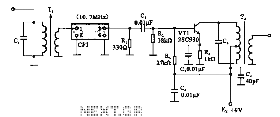
This circuit features a ceramic filter integrated with an FM intermediate frequency (IF) amplifier. The FM IF amplifier circuit primarily consists of an input variable voltage regulator (T), ceramic filters (CF1), and additional components such as the IF amplifier...
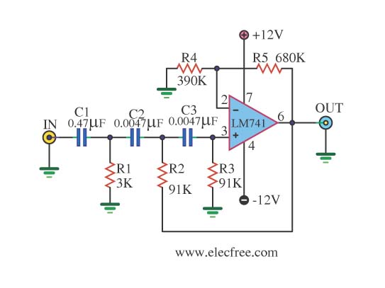
This is a simple high-pass filter that performs filtering at high frequencies. It can only change these frequencies using the IC 741, which is an integrated circuit operational amplifier used in the circuit. The high-pass filter designed with the IC...
The input signal is processed with an electronic low-pass filter to eliminate all frequencies above the Nyquist frequency, which is half of the sampling rate. This process is essential to prevent aliasing during sampling and is referred to as...

In this arrangement, a high-value inductor or choke L is connected in series with the rectifier element and the load. The filtering action of an inductor filter depends on its property of opposing any change in the current flowing...
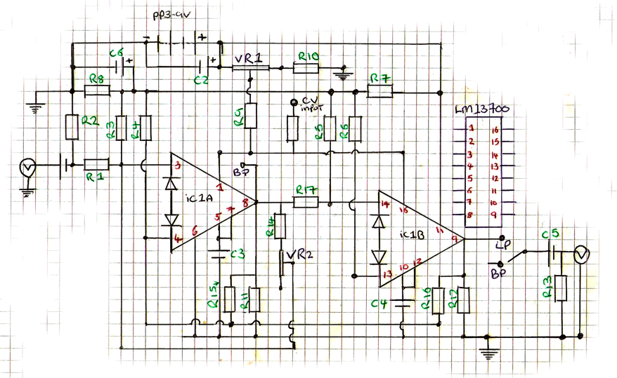
This is a 9V DC powered LM13700 dual transconductance operational amplifier-based filter, highly suitable for battery-powered circuits. The design is adapted from an article by R. A. Penfold for Maplin magazine, incorporating manual filter cut-off and resonance control. At...
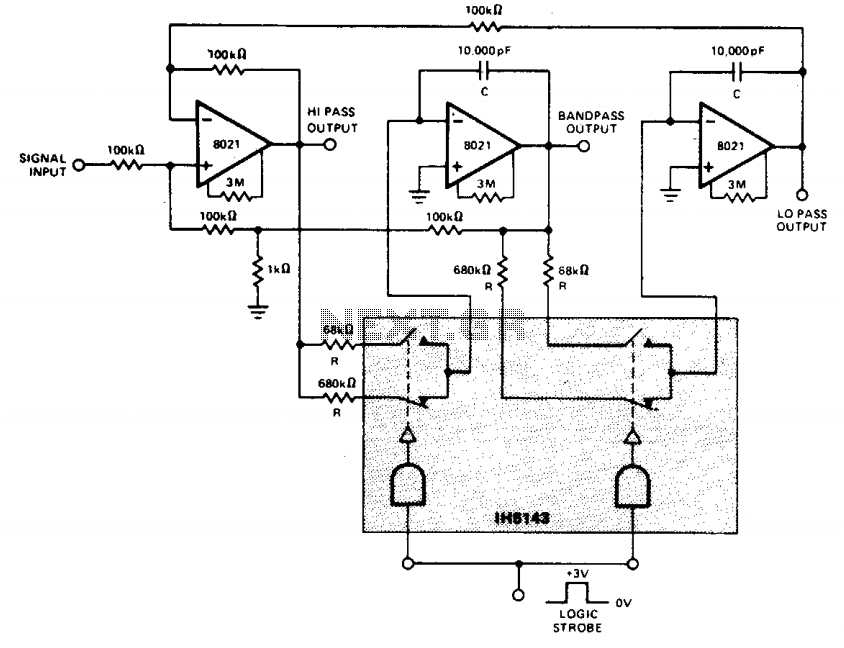
This constant gain, constant Q, variable frequency filter provides simultaneous low-pass, bandpass, and high-pass outputs. With the specified component values, the center frequency will be 235 Hz for high logic inputs and 23.5 Hz for low logic inputs. The...