
SUN TRACKER HITEC SERVO ACTUATOR CONTROLLING ALIGNMENT SOLAR WING PANELS
The described electronic schematic encompasses a robust solar tracking system utilizing servos and advanced control circuits. The system employs large servos capable of precise movement to adjust the angle of solar panels, maximizing sunlight exposure throughout the day. The use of the LM339 comparator circuit allows for effective signal processing from the sensor array, which detects the sun's position by comparing the intensity of light received by the east and west-facing LEDs. The circuit's design ensures that the servos only respond to significant changes in light intensity, thereby reducing unnecessary movement and mechanical wear.
The integration of a PIC microcontroller enhances the system's functionality, enabling programmable features that can be tailored to specific applications. The pre-programmed PICAXE chip simplifies the setup process for hobbyists while allowing for advanced modifications. The dual-mode update rate feature is particularly noteworthy, as it balances responsiveness with the longevity of the mechanical components.
Overall, this solar tracker circuit kit represents a sophisticated solution for solar energy optimization, combining analog and digital technologies to create a versatile and efficient tracking system. The inclusion of limit switches and photocell sensors further ensures operational reliability and safety, making it suitable for various applications in solar energy harnessing.The giant (by radio control standards) servos above are shown adjacent to a Nokia 3310 mobile phone to give an idea of the scale. The arms are 12cm long - perfect for lifting a bank of solar panels (wing). Our local Model Aerodrome in Seaside Road, Eastbourne, supplied these beauties, taking the trouble to source one unit from afar - not the kind
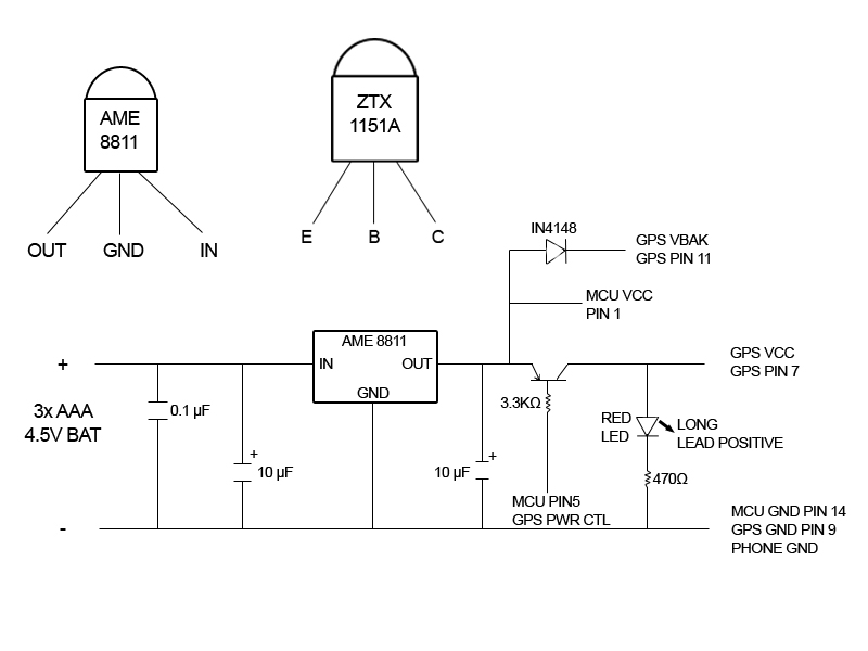
of thing you are asked for every day. Thanks to Dave and Steve for helping us out of a tough spot. The Model Aerodrome were also able to match a reduction gearbox shown elsewhere on this site under catamaran model drive-train. On this page we also look at two electronic design solutions for control of our wing angle. One is an analogue comparator based circuit, the other a digital computer chip based circuit. They both do the same thing, but with different features. The LED arrangement in the LM339 circuit below uses two rows of three LEDs with each LED connected in parallel, the two rows are connected in parallel but reversed polarity.
The sensor array is made with three west LEDs and three east LEDs. A 1meg resistor and a 10n ceramic capacitor (103z) are also in parallel with the sensor. The sensor LEDs provide input voltage for two comparators on the LM339 chip with the variable resistor R2 providing a "dead zone" or sensitivity adjustment. Each comparator output is fed into a transistor Darlington pair which in turn drives the DC motor. The rail voltages are provided by two batteries connected in series with the center tap providing the ground reference.
The developers at Green Watts have tested this circuit with 2 single cell lithium-ion batteries providing +/- 4. 2 volts and two 12 volt lead batteries, the LM339 is rated for input voltages from +/- 2 volts to +/- 18 volts.
This special COMPUTER CHIP CONTROLLED SOLAR TRACKER CIRCUIT KIT (Catalog #ST2-HD-PIX) from MTM Scientific is a new product they are making available on a limited basis for advanced electronic hobbyists. Identical in function to their other Solar Tracker Kits, this kit contains all the electrical components for building the circuit (shown above) to automatically find and follow the sun across the sky.
Just like their other kits, this tracker circuit finds the sun at dawn, follows the sun during the day, and resets to home at nightfall for the next day. This kit is ideal for driving a single axis solar tracker with a 12 VDC gear motor or linear actuator that they don`t provide.
Also included, but not shown, are the same 2 photocell sensors, 2 limit switches and 20+ page booklet they include with all their Solar Tracker Kits. So what is different about this kit This new version of our Solar Tracker Kit is controlled by a PIC micro-controller running a computer program written in PICAXE BASIC.
Much more information about the Picaxe family of micro-controllers is available at Phil Anderson`s website ( The Picaxe Chip can be reprogrammed using the serial port of your computer using the Picaxe Development Platform Software (Download and Installation required). Obviously that would be a project for advanced hobbyists capable of reading and writing computer line code and reading circuit diagrams.
Note: We provide the Picaxe chip already programmed for this kit. 1) The Tracker has a FAST/SLOW update rate limit which only allows position changes once every 1 minute, or once every 10 minutes. This feature reduces wear and tear on the mechanical and electrical hardware. 2) The Tracker has a software feature which requires all motion updates to be of 1/10 second duration or more, to reduce `jogging` and `hunting`.
essentially software controlled hysteresis. What are some ideas for advanced applications Advanced hobbyists might consider writing code to do optimized sunlight threshold detection, smart parking, historical data analysis, bright cloud ignore, heliostat applications and really. just about anything imaginable. MMT are interested to know more about you 🔗 External reference
Related Circuits
The tracker is straightforward to construct on a perfboard. A basic one-pad-per-hole perfboard and 26-gauge wire are recommended, although 30-gauge wire may be more suitable. All electronic components can be sourced from Mouser Electronics, while Radio Shack offers the...
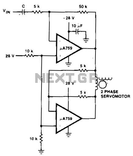
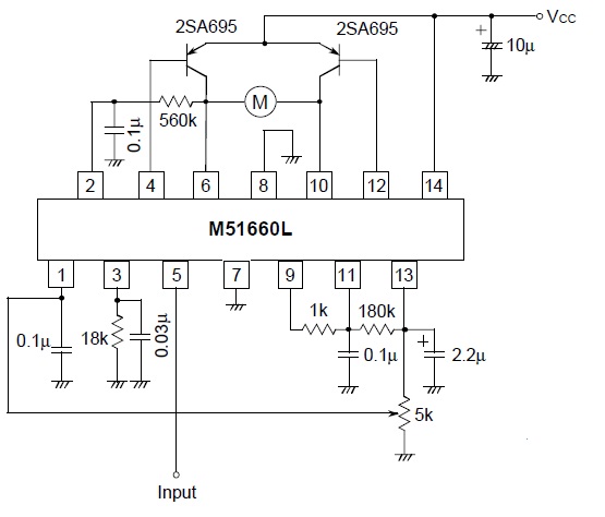
This motor driver circuit utilizes a p.A759 power amplifier to drive a two-phase servomotor. The motor driver circuit is designed to efficiently control a two-phase servomotor, leveraging the capabilities of the p.A759 power amplifier. This amplifier is specifically chosen for...
This project uses the 1.2v rechargeable battery and solar panel from a Solar Garden Light. These lights can be bought for less than $5.00 in most $2.00 shops or similar shops that sell general household items. We are also...
The Up Alarm is designed to provide an audible alert when sunlight is detected or when a light source is activated in a dark environment. It can also be utilized to sense various light sources such as beams or...
A servo is a compact motor capable of precise positioning at various angles. It incorporates internal circuitry designed to maintain its position automatically. A servo motor typically consists of a DC motor, a gear system, a potentiometer, and a control...
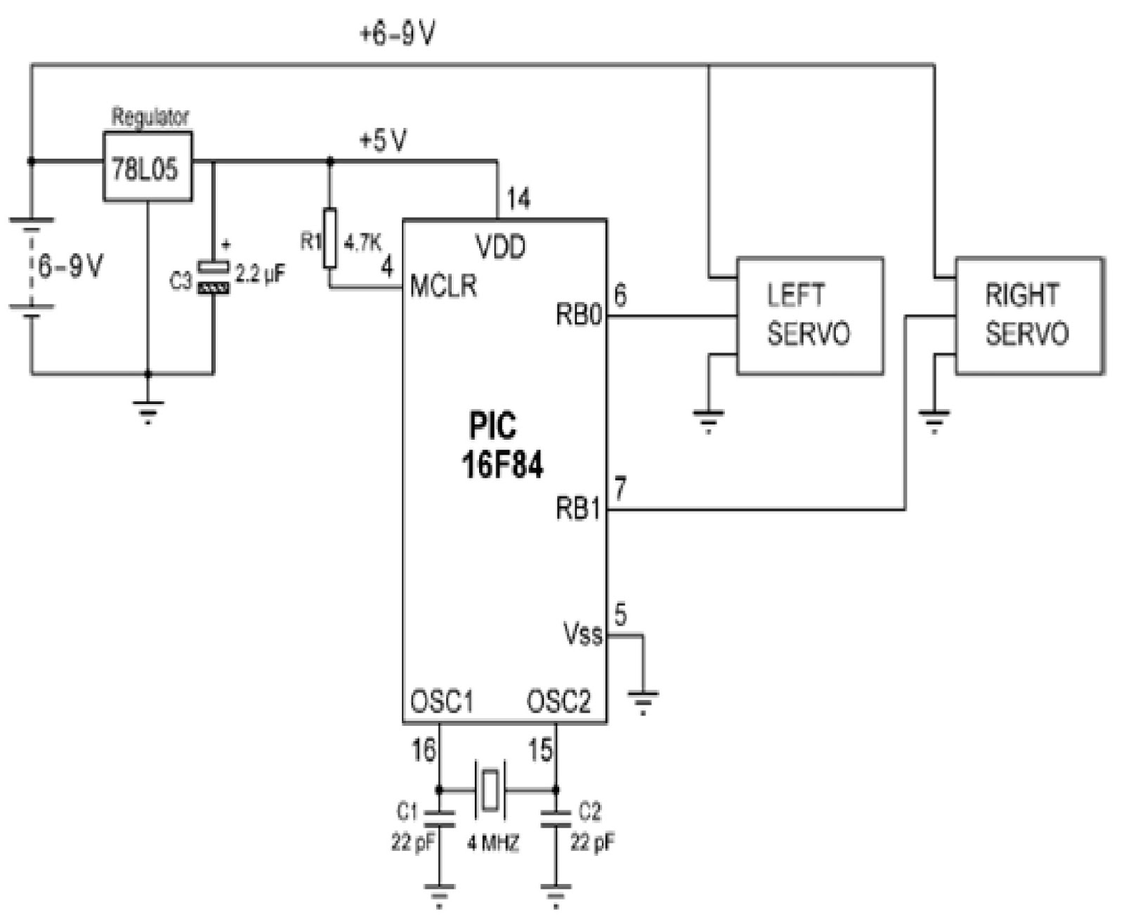
Mobile robots are utilized in various industrial, commercial, research, and hobby applications. This project focuses on controlling a mobile robot using servomotors. The robot is based on a well-known mobile robot called Boe Bot, developed by Parallax. The basic...