
Super Class-A 30W Amplifier


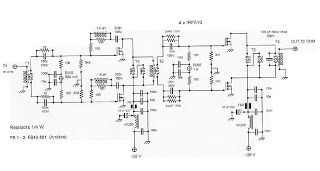
The described amplifier is a modified version of Jean Hiraga's Super Class-A 30W amplifier, featuring a robust output stage utilizing Toshiba 2SA1943 and 2SC5200 complementary transistor pairs. This selection of transistors facilitates an increased rail voltage, enhancing the amplifier's power output capability. The PCB layout retains the original design, ensuring familiarity and reliability in assembly.
Biasing is set at approximately 1.65A at 35V, leading to a continuous dissipation of around 58W per output transistor, which is a third of their maximum rating of 150W. The choice of 1W carbon bias resistors is notable for their thermal stability, which is critical in high-power applications. The circuit also incorporates 0.6W metal film resistors, which were replaced with 2W types to better handle thermal loads, as indicated by the heat marks observed during operation.
Thermal management is a significant consideration in this design, with a heat sink measuring approximately 420 x 180 x 35 mm, effectively dissipating heat generated by the output stage. The enclosure is constructed from aluminum, with a 3 mm thick top and base plate, and features countersunk stainless fasteners (M5 and M3) for secure assembly.
The power supply comprises a 500VA potted toroidal transformer, complemented by a regulated supply for the DC protection circuit and an RF filter to mitigate interference. The capacitor bank has been upgraded to six 220,000 µF capacitors, totaling 1.2 Farads, to ensure ample power storage and stability during operation.
Performance measurements indicate that the amplifier operates with a frequency response down to -3dB at 208kHz, capable of delivering the rated power output efficiently. The amplifier is characterized by its ability to produce rich sound quality, maintaining low-level detail and an effortless presentation, hallmarks of Class-A amplification. The modifications and enhancements made to the original design aim to optimize performance while preserving the integrity of the original circuit topology.I used the original board layout shown in the magazine article as well as the original driver transistors. However, due to the unavailability of the original power transistors, I opted for a more robust output stage using Toshiba 2SA1943 and 2SC5200 complimentary transistor pairs.
This transistor change also allowed me to increase the rail voltage which allows the amplifier to deliver more power. The schematic for my version of the Jean Hiraga's Super Class-A 30W Amplifier is shown.. Above you can see the PCB with all components, note the bias resistors which are 1W carbon types I found they had better thermal stability in this application. The heat marks at the end of the legs of the resistors next to the Sprague Orange drop capacitor are from 0.6W metal film resistors which were operating at their thermal limit and were subsequently replaced with 2W metal film types.
My version of the Jean Hiraga Super Class-A Amplifier is running at a bias of about 1.65A @ 35V resulting in about 58W of continuous dissipation per transistor in the output stage (just over 1/3 their rating of 150W). As you can imagine, the heat sink runs quite hot, approximately 40 Celsius (100F) above room temperature.
The enclosure work is all done by hand using aluminum. Channel sides, 3 mm top plate, 3 mm base plate. The heat sink is comprised of two pieces cut to size and is approx 420 x 180 x 35 mm. The fasteners are mainly countersunk stainless M5 or M3 stainless. Heat sinking was increased. The capacitor bank was also increased to six 220000 uF capacitors (yes that is 1.2 Farads). A 500VA potted toroid transformer was used for the supply. I have added a small toroid for a regulated supply running the DC protection circuit which I added. There is also a RF filter in the supply line. I am very happy with the sonic results of this amplifier. Jean Hiraga's deceptively simple and pure circuit topology once again shines through. The sound seems effortless and gives the impression of a much higher power amplifier yet still being able to produce all the low level details, the sound which Class-A is renowned for.Various measurements of the amplifier on an oscilloscope are shown in the photographs below. The amplifier is down -3dB at 208kHz and can deliver 58W at full power. 🔗 External reference
Related Circuits
This amplifier does not claim to be state of the art, and in fact the base design is now over 20 years old. It is a simple amp to build, uses commonly available parts and is stable and reliable....
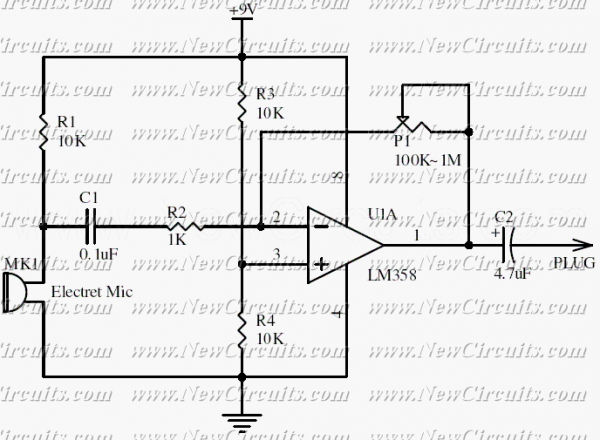
This circuit will be useful if you have an electret microphone that produces a low audio (sound) level and you want to connect it to an amplifier or something like it. The circuit boosts the microphone output voltage to...
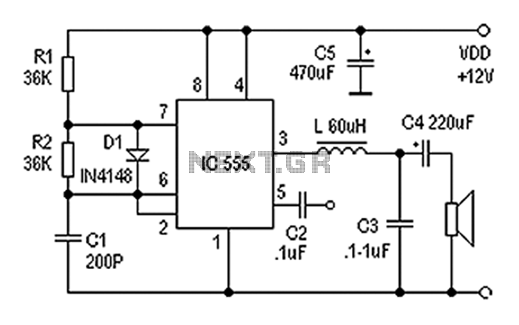
Also known as a digital amplifier, the Class-D amplifier is characterized by its compact size and high efficiency. This circuit utilizes a 555 timer IC to create a Class D amplifier. The 555 timer operates as a controllable multivibrator,...
The preamp circuit is completely conventional, and by necessity is AC coupled throughout. The artificial earth is derived by two resistors (R1 and R2), which will set the "earth" at exactly 1/2 the supply voltage. This is nominally 13.8V...
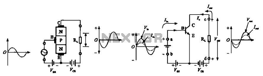
The common emitter amplifier circuit exhibits a specific phase relationship between its input and output signals. This configuration is widely utilized in various electronic devices primarily for its high voltage gain. However, the output impedance is higher than the...
This is an RF Power Amplifier designed for low-cost QRP applications. The circuit operates over a broadband frequency range of 1.8 to 30 MHz, eliminating the need for tuning. The only adjustment required is to set the quiescent current...