
Dynamic braking circuit control thyristor

The circuit operates by integrating a thyristor for effective braking control, which is particularly advantageous in applications involving small capacity asynchronous motors. The design eliminates the need for a step-down transformer, simplifying the circuit and reducing potential losses associated with transformer use.
During operation, when the motor is to be shut down, the contactor KM1 is de-energized, allowing contactor KM2 to energize the brake circuit. This energization triggers the thyristor V, which conducts during the positive half cycle of the AC power supply. The conduction of the thyristor allows pulsed DC current to flow to the motor, creating a braking effect that slows down the motor effectively.
The motor remains in a braking state as long as the thyristor is conducting. The circuit is designed with a time delay relay KT, which plays a crucial role in the braking process. The normally closed (NC) contact of this relay remains closed during the braking operation. Once the predetermined time delay elapses, the relay opens its NC contact, causing contactor KM2 to de-energize and subsequently release the brake circuit. This ensures that the braking process is terminated safely and efficiently, preventing any abrupt cessation that could potentially harm the motor or associated components.
Overall, this thyristor-based braking control circuit provides a reliable and efficient means of controlling the braking of small capacity asynchronous motors, enhancing the operational safety and longevity of the motor system. Circuit shown in Figure 3-148. The circuit eliminates the need for step-down transformer, using thyristor for brake control, for small capacity asynchronous motor braking amoun t. When shut down, the contactor KM] release, KM2 pull the brake circuit to work, triggering the thyristor V conduction (per power supply positive half cycle conduction), the motor continues to give effect pulsed DC current braking, the motor is braking status. Until the time delay relay KT break NC contact is opened, the contactor KM2 release, before the end of the braking process.
Related Circuits
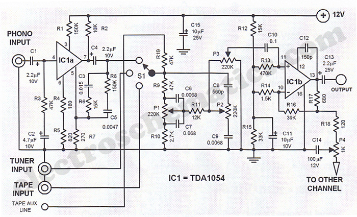
This Hi-Fi stereo preamplifier circuit is designed using the TDA1054 integrated circuit from SGS. The TDA1054 is a 16-pin DIL package that incorporates two separate preamplifier circuits. It is a low-noise preamplifier with minimal complications in the design process....
The remote control electric hoist control circuit comprises a wireless transmitter, a wireless receiver control circuit, and a main control circuit. The wireless transmitter utilizes the TWH9326 four-key BP transmitter. The wireless receiver control circuit includes a power supply...
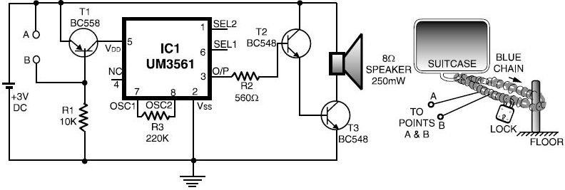
This luggage or bike alarm can be utilized while traveling by train or bus. Typically, luggage is secured using a chain-and-lock arrangement; however, there are still vulnerabilities. The luggage or bike alarm system is designed to enhance the security of...
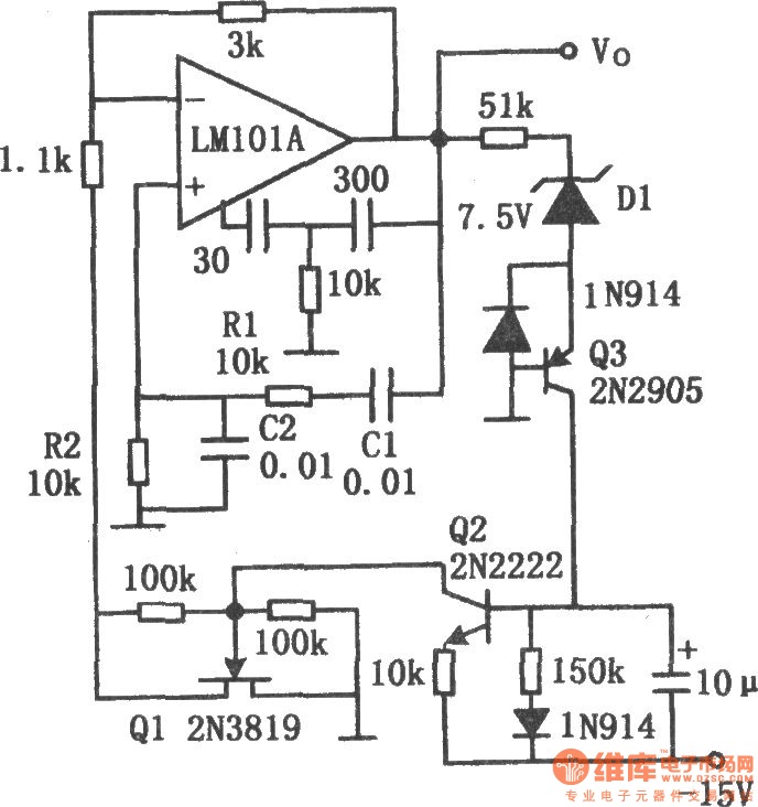
The chart illustrates the Wien bridge sine wave oscillator circuit. The amount of negative feedback in the circuit is determined by the internal resistance of the FET. When the peak output voltage of the oscillator reaches the regulated voltage...
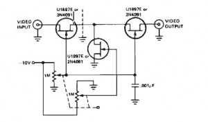
A variable gain amplifier controlled by voltage, functioning as a video amplifier. It utilizes three Field Effect Transistors (FETs) of type U1897E, which can be substituted with 2N4091. The described variable gain amplifier is designed to adjust its gain based...
The primary function of the optical receiver is to extract information encoded on a modulated light carrier from a distant transmitter and restore it to its original form. A typical through-the-air communications receiver can be divided into five distinct...