
Super Simple Inverter

The described inverter circuit is designed to convert a low voltage direct current (DC) input into a high voltage direct current output, suitable for powering devices such as fluorescent lamps and small strobe lights. The circuit typically operates by utilizing a transformer to step up the voltage from the input level of 12 VDC to an output exceeding 400 VDC.
Key components of this inverter may include a switching element, such as a transistor or MOSFET, which is responsible for turning the current on and off rapidly to create an alternating current (AC) signal. This AC signal is then fed into a transformer, which increases the voltage to the desired level. The output is rectified to provide a stable DC voltage suitable for the load.
The inverter circuit may also incorporate additional components such as resistors, capacitors, and diodes to ensure stable operation, manage voltage levels, and filter noise. A feedback mechanism may be included to regulate the output voltage and maintain consistency under varying load conditions.
Safety precautions are critical when designing and implementing this inverter, particularly due to the high voltages involved. Proper insulation, circuit protection, and adherence to safety standards are essential to prevent electrical hazards.
Overall, this inverter circuit represents a practical solution for applications requiring high voltage DC power from a low voltage DC source, making it versatile for various electronic projects.This is example of a simple inverter that can be used to power fluorescent lamp and a small strobe. This circuit will produce over 400VDC from a 12 VDC, 2.5 A.. 🔗 External reference
Related Circuits
This project is based on modifications of existing circuits, primarily inspired by Jack Bryant's one-tube superheterodyne contest radio project. The circuit design was influenced by valuable suggestions from fellow radio enthusiasts Ben Tongue and Mike Peebles. The radio is...
Q1 and Q2, along with T1, determine the wattage output of the inverter. Using Q1 and Q2 as 2N3055 transistors and T1 rated at 15 A, the inverter can provide approximately 300 watts. Substituting larger transformers and more powerful...
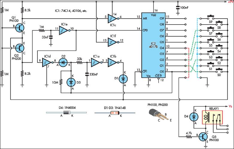
This simple combination lock accommodates codes from 1 to 9 digits long, with the only restriction being that the same digit cannot be used twice. The circuit is designed for a 4-digit code, illustrated by the example "2057". Any...
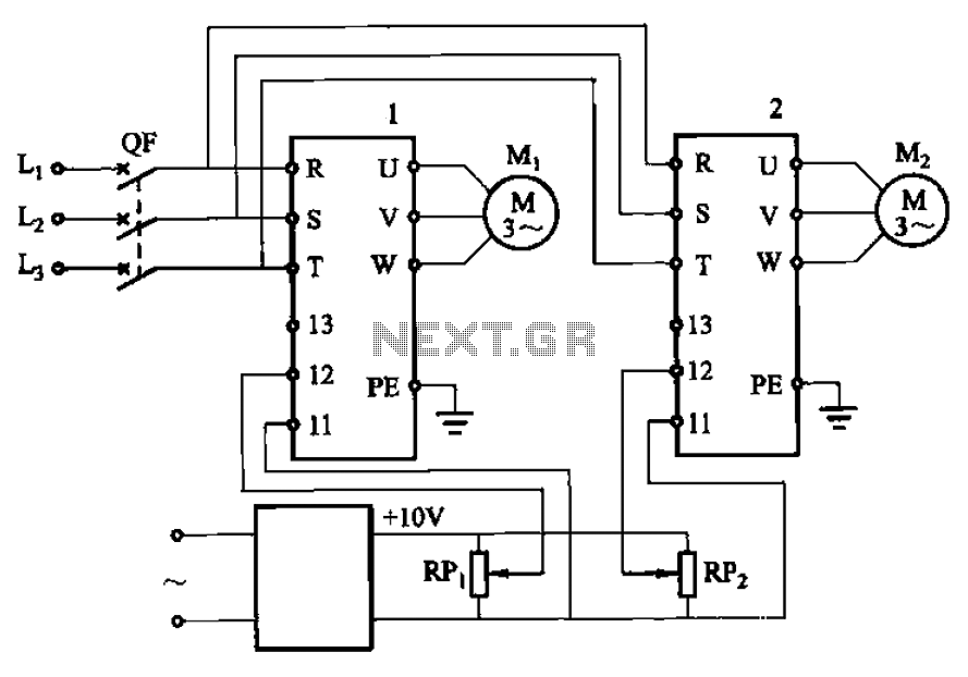
Adjust the potentiometers RPi and RPz to modify the speed of two motors. The circuit utilizes two potentiometers, designated as RPi and RPz, to control the speed of two separate motors. Each potentiometer is connected in a voltage divider configuration,...

Laptop computers frequently utilize large-screen LCDs that require both a variable and a negative supply to achieve maximum contrast. This circuit operates from the system's positive battery supply and generates a digitally variable negative voltage to drive the display....
Figure 14-41 illustrates a multivibrator circuit utilizing a 555 timer alongside various capacitive and resistive components. The oscillation frequency is determined by the values of Ra, R16, and C3, following the formula f = 1.44 / ((Ra + 2R16)...