
Supercharged Joule circuit

The circuit schematic in question likely includes various electronic components arranged to perform a specific function. Typically, such schematics are used to illustrate the connections and relationships between components like resistors, capacitors, diodes, transistors, and integrated circuits. Each component is represented by standardized symbols, and the connections are depicted by lines that indicate electrical pathways.
In a well-designed schematic, components would be labeled with their values and specifications, such as resistance in ohms for resistors or capacitance in farads for capacitors. The power supply would also be indicated, showing the voltage levels required for the circuit to operate effectively. Ground connections are usually marked to establish a common return path for the current.
Furthermore, the schematic might include additional annotations or notes that clarify the functionality of specific sections of the circuit. For example, it could specify which components are part of a feedback loop, which are responsible for signal amplification, or those that filter out unwanted noise.
Overall, a comprehensive schematic serves as a crucial tool for engineers and technicians, allowing for easier troubleshooting, modification, and understanding of the circuit's operation. It is essential that such documents are accurately prepared and made accessible to ensure that the intended audience can utilize them effectively.I think this picture and schematic was posted to my watsonseblog. but it didnt get posted to this 🔗 External reference
Related Circuits
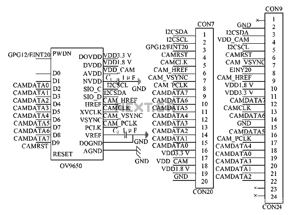
The circuit principle involves the OV9650 processor, which interfaces through three components: the SCCB interface, the data output interface, and the control interface. The SCCB interface is responsible for transferring initialization parameters from the processor's internal registers. It utilizes...
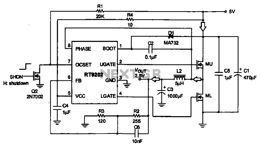
A 5V to 2.5V voltage regulator circuit is designed for use in computer motherboards. At its core, this circuit utilizes the RT9202 power management chip. The RT9202 functions as a switching pulse generating circuit, which, upon startup, converts a...
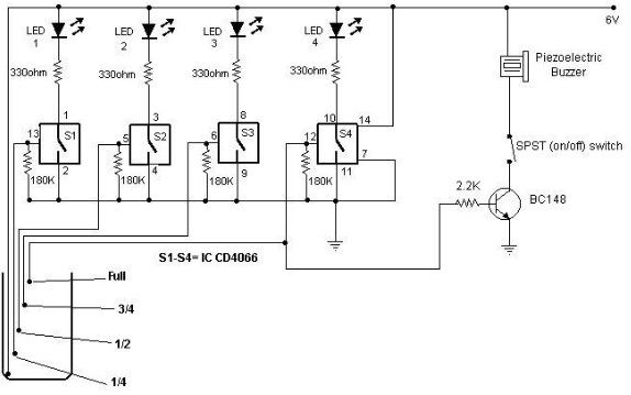
A low-cost water level indicator circuit can be designed using this schematic. This water level indicator utilizes a CMOS IC, the CD4066, to indicate the amount of water present in an overhead tank and provides an alarm when the...
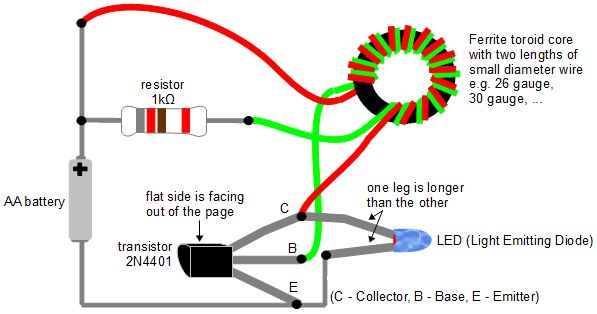
The Joule Thief is an electronic circuit designed to utilize batteries that are typically deemed dead. A battery is often labeled "dead" when it can no longer power a specific device. However, the underlying issue is that the battery...
The circuit below illustrates generating a single positive pulse which is delayed relative to the trigger input time. The circuit is similar to the one above but employs two stages so that both the pulse width and delay can...
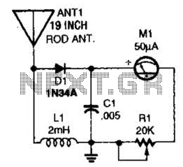
This basic field-strength meter offers an affordable solution for monitoring an amateur radio or CB transmitter, as well as an antenna system, to ensure maximum output. The field-strength meter is designed to measure the strength of radio frequency (RF) signals...