
Supply Voltage Monitor with 555 IC

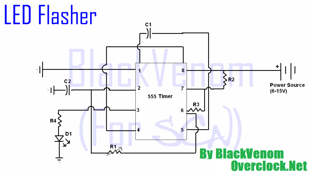
The supply voltage monitor circuit utilizes the versatile 555 timer IC, which operates in a comparator mode to monitor the voltage level of the power supply. When the supply voltage exceeds a predetermined threshold, the circuit activates an output signal, typically in the form of an LED indicator. This LED will illuminate, providing a visual indication that the power supply is functioning properly.
The circuit can be configured with a voltage divider network to set the reference voltage against which the supply voltage is compared. Resistors R1 and R2 form this voltage divider, and the values can be adjusted to set the desired threshold level. The output of the 555 timer can be connected to a transistor for driving larger loads, such as an alarm or additional indicators, enhancing the circuit's functionality.
Additionally, the 555 timer can be powered by the same voltage it is monitoring, making it a self-sufficient solution. The design should also incorporate protective components, such as Zener diodes or fuses, to safeguard against overvoltage conditions. This ensures that the circuit remains operational and reliable under varying conditions.
In summary, this supply voltage monitor circuit provides an effective means of ensuring that power supply levels remain within acceptable limits, thus preventing potential damage to connected devices and enhancing overall system reliability.This is a supply voltage monitor circuit, an indicator to show if the power supply is in good condition. Designed using the IC 555 timer, this circuit will.. 🔗 External reference
Related Circuits
It is advisable to prototype the entire circuit using a breadboard. This method simplifies the process significantly compared to attempting to determine the connections on a small printed circuit board. Prototyping a circuit on a breadboard allows for easy modifications...
All of the components in this list are generally available through RadioShack for less than $20. It is highly recommended to use a breadboard for assembly, as mistakes are common for first-time builders, and soldering can complicate troubleshooting. This...

The VCO is based on a Hartley oscillator. The frequency is determined by L1 and capacitor C1. The tuning voltage will change the capacitance in the varactor BB132 which will change the oscillation frequency. The value of capacitor C2...
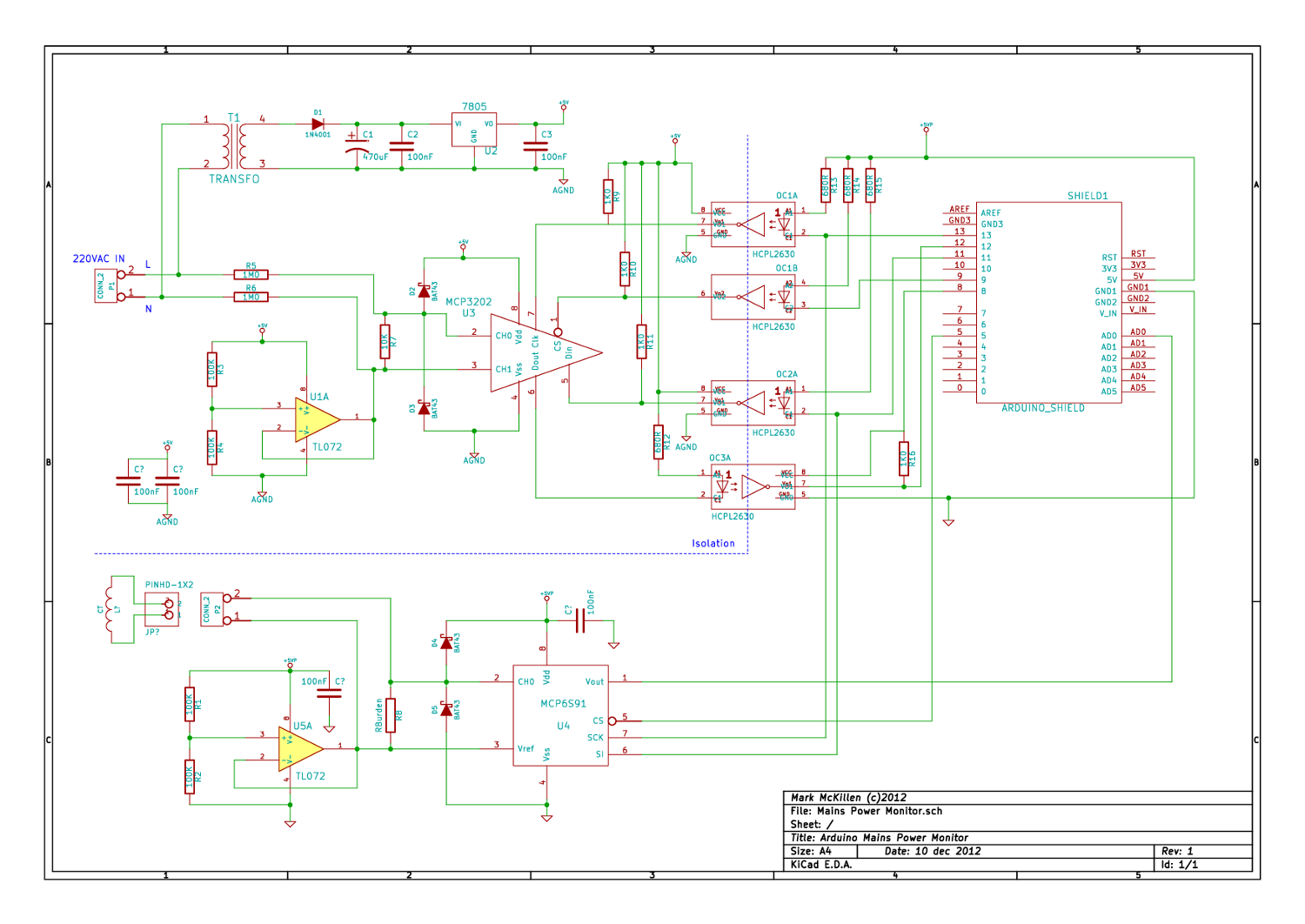
A mains (220-240VAC) power monitoring circuit has been sought for interfacing with an Arduino. While the OpenEnergyMonitor solution employs a transformer for isolation and measurement of mains voltage, it has been noted that the transformer does not couple effectively...
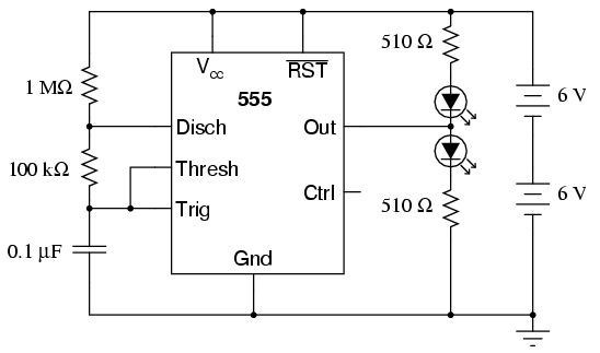
The 555 integrated circuit is a versatile timer that can be used for various applications. This experiment focuses on its operation as an astable multivibrator or oscillator. When connected to a capacitor and two resistors, it generates a square-wave...
The Car Voltage Gauge is based on 3 parts. The input circuit is an Analog to Digital Converter (IC2 CA3162E). The purpose of this chip is to sample an analog voltage and convert it to a decimal value which...