
Suspended Bicore circuit for robots

The bicore circuit is a fundamental component in the BEAM robotics platform, primarily functioning as an oscillator. The core functionality is derived from its ability to produce alternating signals that can be used to control various robotic functions. The outputs of the bicore oscillate in a specific pattern, which can be described as (+ -, - +, + -, - +). This behavior allows the circuit to drive motors or control LED indicators, depending on the application.
Central to the operation of the bicore is the resistor R1, which dictates the frequency of the oscillations. The choice of resistor value significantly influences the performance characteristics of the circuit. For rapid oscillations, a lower resistor value is preferred, while a higher value results in slower oscillations. It is common practice to select resistor values within the range of 100K to 10M, with 1.6M being a frequently utilized value.
The circuit also incorporates a capacitor, typically a 0.22uF capacitor, which works in conjunction with R1 to stabilize the oscillation frequency and shape the waveform output. The integration of a 74AC240 buffer/driver IC enhances the circuit's capability, allowing for greater control over the output signals and facilitating the driving of larger loads, such as motors.
In practical applications, the bicore can be utilized in a variety of configurations. For instance, in photovores, the oscillating output can be used to control motors that steer toward light sources. Similarly, in robotic walkers, multiple bicore circuits can be combined to coordinate the movement of several motors, enabling complex locomotion patterns. The versatility of the bicore circuit makes it an essential building block for intermediate to advanced BEAM robotics, where multiple units can be interconnected to create sophisticated robotic systems capable of performing a wide range of tasks.The bicore is the basis of advanced BEAM! Most intermediate to advanced BEAM robots are built off of the bicore. Uses go all the way from photovores to servo motor drivers to walkers to.... You get the idea. What it is is basically just an oscillator who's outputs go (+ - , - +, + -, - +....) and the rate of oscillations is controlled by the resister (R1). Another cool thing is that they can be grouped together to form large complex structures. Really a very cool circuit once you figure out how it works. R1 R1 controls the rate of oscillation. If you want quick oscillations you use a low value resister, long oscillations you use large value resister.
I normally don't use values below 100K or over 10M, 1.6M is a common value. As I noted above it has a very wide range of uses. Photovores, light seeking heads, walkers, servo motor drivers.... Just to name a few. The walker category is HUGE!! There's walkers with 2 motors to 12 motors. No sensors to electronic compasses and sonar. A single bicore can't do much other than blink a couple LEDs or make a motor go back (which is sometimes what you might want) but they are most useful in groups. R1 (see circuit notes) 1 Digikey See circuit notes .22uF Capacitor 2 Digikey P4966-ND 74AC240 1 Digikey 74AC240PC-ND
🔗 External reference
Related Circuits
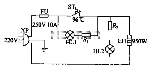
The 220V electric vibrator features a clip for insertion, with FU representing the fuse. ST indicates an inverter-like device, while HL1 and HL2 serve as indicators for insulation and heating. The EH component functions as the heater. When the...
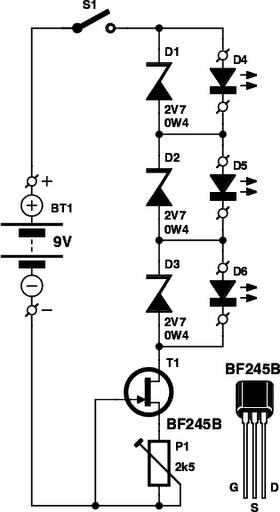
These small electronic lamps are quite practical and have a long lifespan. Approximately 40 years after Nick Holonyak invented the first LED, they have become nearly essential. Any dedicated electronics enthusiast typically keeps a few in their collection. Prior...
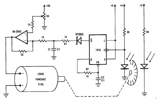
A simple encoder circuit for a DC motor can be constructed using this circuit diagram. The system consists of the HA-2542, a small 12-V DC motor, and a position encoder. During operation, the encoder generates a series of constant-width...
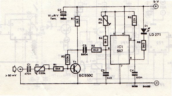
The transmitter is equipped with an LM567 tone decoder circuit. An audio signal (at least 50 mV peak-to-peak) is amplified with a transistor (T1) and then used to modulate IC1. The infrared transmitter frequency is adjusted with potentiometer P2...

The DC current negative feedback BTL circuit illustrated in Figure 2 eliminates the standard BTL circuit capacitors C12 and C22, which affects the DC characteristics of the circuit. Resistors R16 and R26 function as sampling resistors, while R15, R16,...
The luminescent diode (LED) is constructed from gallium arsenide (GaAs), a specialized semiconductor material, and gallium arsenide phosphide. It can be used individually or assembled into segment-type or lattice LED display devices. The display unit consists of a sectional...