
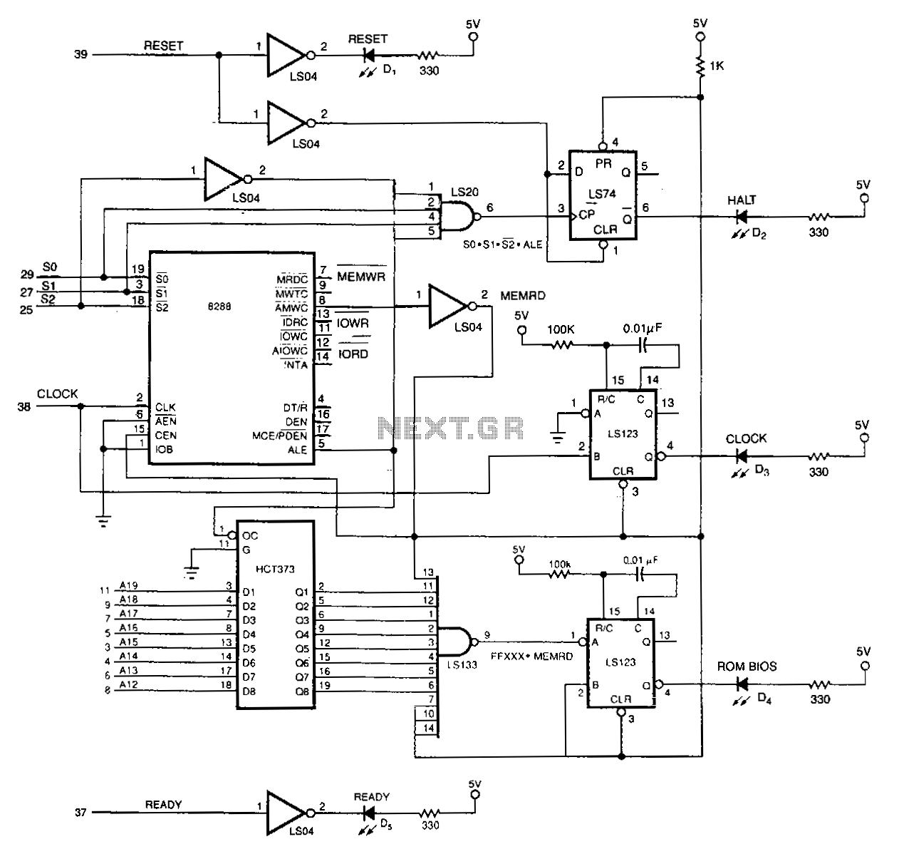
Swept sine oscillator has quadrature output

The MAX038 oscillator chip is a versatile component utilized for generating various waveform outputs, including sine, triangle, and square waves, making it suitable for a range of applications in signal processing and analysis. The ability to sweep frequencies over a wide range allows for dynamic testing and analysis of systems, especially in low-frequency applications. Its architecture includes a phase detector that facilitates the generation of quadrature signals, essential for demodulation and phase analysis in various electronic systems. The phase detector's operation, in conjunction with the SYNC and OUT signals, enables precise control of phase relationships, which is critical in applications such as PLLs and frequency response analysis. The design considerations for loading and impedance are important for maintaining the integrity of the output signals, ensuring that the oscillator performs reliably under varying conditions. The MAX038's features, combined with its ease of use, make it a valuable tool for engineers working on signal generation and analysis tasks.Signals with a know frequency but unknown phase may be detected using an in-phase and a 90 ° shifted reference signal, as frequently used in lock-in amplifiers, synchronous detectors, and frequency-response analyzers. The 90 °-shifted signal is called the quadrature signal. By multiplying the received signal with the reference signals, the low-pas s filtered outputs will represent the real and imaginary components of the received signal. Once the two components are known, this complex number can be converted into amplitude and phase. When used for frequency response analysis, the system is excited with a sine signal and the output of the system is demodulated using the two references. Neglecting harmonics, the multiplication can be performed using square-wave reference signals, which control amplifiers with a digitally controlled gain of either +1 or ’1.
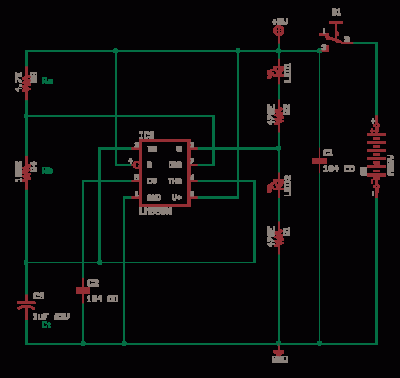
The frequency must be swept over the range of interest. Designing a swept-sine generator with quadrature output isn`t a trivial task, though. For low-frequency purposes, an undocumented feature of Maxim`s MAX038 oscillator chip makes this easy. The MAX038 is a sine, triangle, and square-wave generator whose frequency can be swept over 2 to 3 decades by a control current.
By switching the frequency-determining capacitor, this range can be considerably extended. The MAX038 has an OUT signal output and a SYNC logic level output (when powered by ±5 V). The SYNC output always has a 50% duty cycle, but the duty cycle of the output signal can be adjusted. For quadrature purposes, the output signal should be adjusted to 50% duty. The chip also contains a phase detector that can be used to generate the quadrature. Figure 1 indicates the phase relations of SYNC, OUT, and the phasedetector output (PDO). By setting a constant high or low level at the phase-detector input (PDI), one can select PDO to either lag or lead SYNC by 90 °.
If PDI is connected to the SYNC output instead of a logic level, the frequency of the phase-detector output is twice that of SYNC. Also, the rising edge of PDO coincides with that of SYNC, which is the case for any duty cycle ( Fig.
2 ). The data sheet doesn`t give a detailed description of the phase detector and the circuit driving PDO ”the output is simply described as a current source switching between 0 and 500 µA. This may be the case for its intended use, but not when loaded by a resistor to ground. When left open, the output alternates between about ’2. 3 and +4 V. The negative voltage apparently is an internal level with a source resistance of 10 to 15 k ©. When loaded by 5 k ©, the output swings between about ’0. 7 and +3. 2 V. Being uncertain about the effects of loading on internal chip operation, a high-impedance load (i. e. , a CMOS gate input) is recommended. Ed-The following supplemental information about the MAX038 was provided by Roger M. Kenyon, senior member of the Applications Dept. technical staff at Maxim: Mr. Olsen`s analysis of the relationships between the SYNC pin and the OUT pin is correct. In sinusoidal mode, the rising edge of SYNC corresponds to the rising zero-crossing of OUT. In square-wave mode, the rising edge of SYNC precedes the rising edge of OUT by 90 °. Internally, the input signal received by the phase detector is a 90 ° lag phase-shifted SYNC signal ( Fig.
3 ). Therefore, as demonstrated by Mr. Olsen, if the PDI pin is held high in sinusoidal mode, then a positive edge at PDO corresponds to a valley at OUT and a negative edge at PDO corresponds to a peak at OUT. If PDI is held low, then a positive edge at PDO corresponds to a peak at OUT and a negative edge at PDO corresponds to a valley at OUT.
Because of this internal phase shift, the SYNC and PDO outputs are ideally suited for developing quadrature signals for OUT. A typical application for the internal phase detector involves PLL operation. The signal applied to PDI is compared to the internal SYNC signal 🔗 External reference
Related Circuits
The 20-MHz clock is phase-locked to the 10-MHz NuBus clock of Apple's Mac II. It employs simple and cost-effective CMOS circuitry to generate square waves at 10 MHz and 20 MHz. The output duty cycle settings are not affected...
In this circuit, a square wave is filtered using a high-order low-pass filter designed to eliminate most harmonics of the waveform at a -3 dB frequency. Consequently, the output of the filter is a fundamental sine wave. This technique...

Readback data is applied directly to the input of the first NE592. This amplifier operates as a wide-band AC coupled amplifier with a gain of 100. By directly coupling the readback head to the amplifier, no matched terminating resistors...
A TTL counter, an 8-channel analog multiplexer, and a fourth-order low-pass filter can generate sine waves ranging from 10 kHz to 25 kHz with a total harmonic distortion (THD) better than -80 dB. The circuit employs two cascaded second-order,...
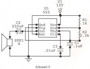
This circuit features an astable oscillator constructed around a 555 timer, generating an alarm tone of 1.8 kHz, which directly drives a speaker. It serves as a fundamental alarm circuit that can be utilized in various projects. Although the...
The LM311 is a comparator that operates from a single 5V supply or dual supplies, with an input current of 150 nA and an output drive capability of 50 V and 50 mA. It features a TTL-CMOS compatible output....