
Switching intensity of LEDs

This circuit can be analyzed as follows: The red 5mm LEDs serve as the primary visual indicators, and their forward voltage drop is typically around 2V. The 3904 NPN transistor acts as a switch, allowing current to flow through the LEDs when the PBNO is pressed. The resistors in the circuit are crucial for limiting the current to safe levels, preventing damage to the LEDs despite simulation predictions.
When the PBNO is not pressed, the transistor remains in the cutoff region, and minimal current flows through the LEDs, causing them to emit a dim light. Upon pressing the PBNO, the base of the transistor receives sufficient voltage to enter the saturation region, allowing a larger current to flow from the collector to the emitter. This results in the LEDs brightening significantly.
It is noteworthy that the discrepancy between the simulation and the actual circuit operation may arise from several factors, including the real-world characteristics of the components used, such as the actual forward voltage drop of the LEDs and the transistor's gain (β). Additionally, if the resistors are adequately sized, they can effectively limit the current to a level that the LEDs can tolerate, thus preventing their destruction.
In practice, the circuit's behavior highlights the importance of component tolerances and real-world conditions, which can differ from ideal simulations. Proper testing and validation of the circuit under various conditions are essential to ensure reliable operation.I built this circuit and for some reason it works. FYI, the diodes are red 5mm LED`s, the transistor is 3904 NPN, and the resistors are what are shown in the schematic. Logically it should not work when you press the PBNO. The red 5mm diodes should be destroyed. According to simulating, the current is above 300mA. How is it pos sible this circuit physically works The lights are dim, then when you press the PBNO, they become bright, which is what I was after. 🔗 External reference
Related Circuits
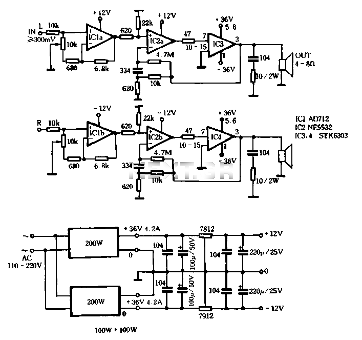
The T amplifier circuit schematic section is illustrated in Figure 3-51. It utilizes the Japan Sanyo STK6303 Pina, which is a high-power thick film integrated circuit. The maximum power supply voltage is 36V, and the output current can reach...
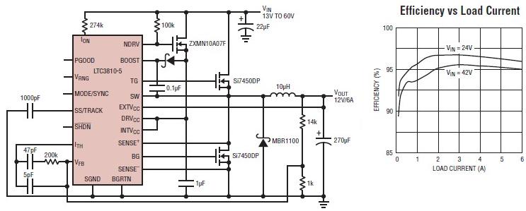
The LTC3810-5 synchronous step-down switching regulator controller allows for the design of a straightforward 12-volt switching power supply electronic project with minimal external components. This controller can directly reduce voltages from up to 60V, making it suitable for telecommunications...
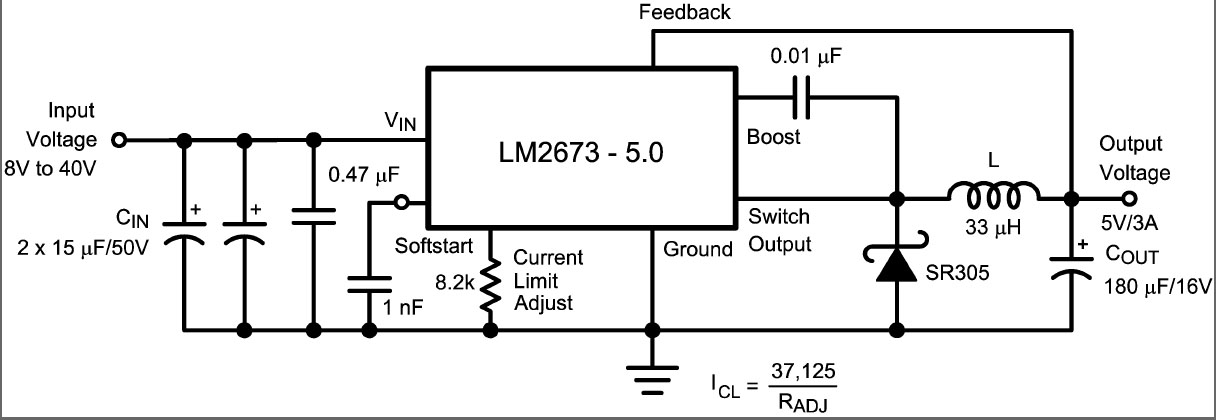
This is a DC switching regulator with an output voltage of 5V and a maximum current of 3A. It is designed for use in digital circuits. The key component of the circuit is the LM2673, which is a 3A...
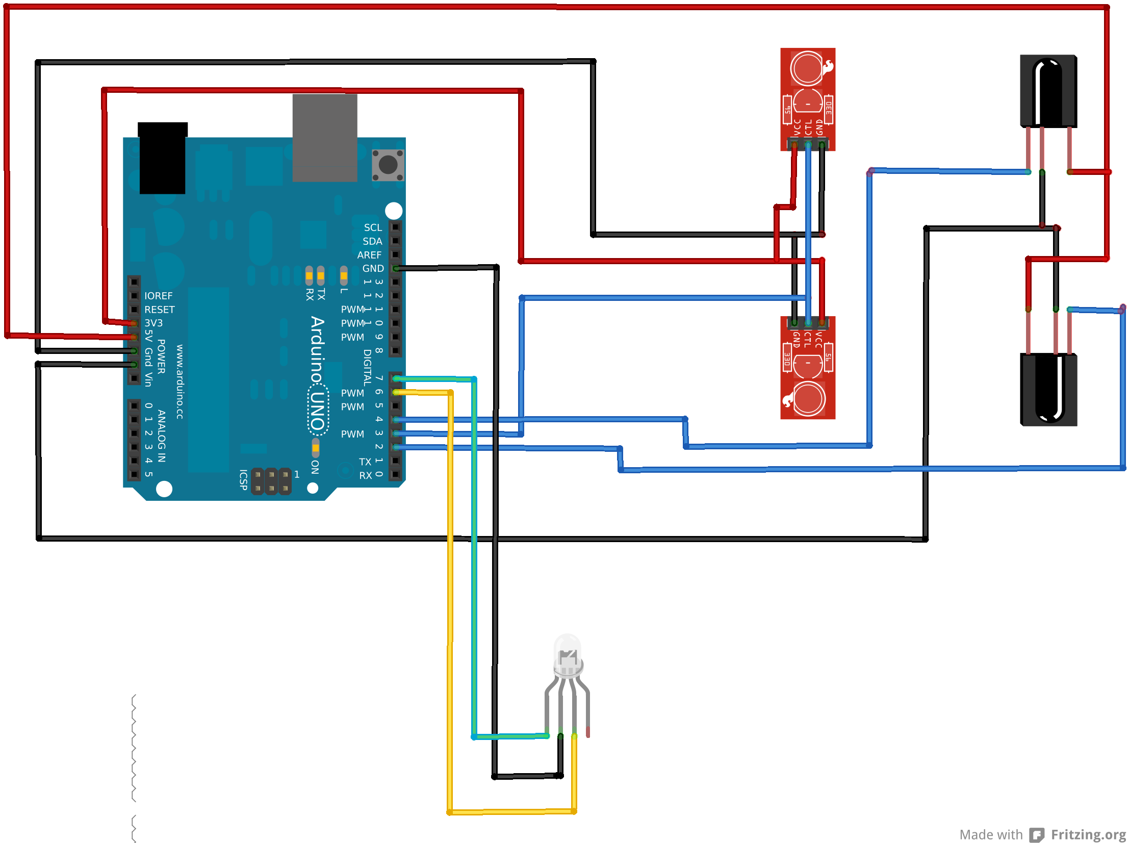
An Arduino Uno is connected to two infrared (IR) transmitters and their respective receivers. When one of the receivers detects a beam break, a strand of LEDs displays a pattern. While this setup functions correctly in principle, an issue...
VD represents the voltage drop across the diode, while VTrans indicates the voltage drop across the transistor. The boundary between continuous and discontinuous operation occurs when the output current (io) is zero. A primary consideration in converter design is...
This document contains a collection of schematic diagrams, datasheets, images, and tips for switch mode power supplies (SMPS) utilizing the TL494, LM339, KA7500, and IC2003 integrated circuits. Switch Mode Power Supplies (SMPS) are crucial components in modern electronic devices, providing...