
Switching power supply circuit with STK6303

The T amplifier circuit is designed to deliver high power efficiency and sound quality, making it suitable for various audio amplification applications. The STK6303 integrated circuit is known for its robustness and ability to handle significant output currents, which is essential in high-performance audio systems. The maximum supply voltage of 36V ensures that the amplifier can operate effectively without distortion at high output levels.
The incorporation of the AD712 op-amp for volume control enhances the circuit's versatility. This op-amp is known for its low noise and high precision, contributing to the overall fidelity of the audio output. The adjustable gain feature allows users to customize the amplification level based on the input signal, which is particularly advantageous in dynamic audio environments where signal levels may vary.
The use of a potentiometer for gain adjustment allows for smooth transitions in volume control, minimizing abrupt changes that can be jarring in audio applications. The high balance of the potentiometer ensures that both channels of the amplifier maintain equal output levels, which is crucial for stereo applications.
The NE5532, as a driving stage, further enhances the circuit's performance by providing a stable gain structure. Its quasi-second mode of operation allows for better linearity and reduced distortion, which is vital for maintaining audio integrity across a range of frequencies. The specified input sensitivity of 300mV indicates that the amplifier can effectively amplify low-level signals, making it suitable for use with various audio sources, including microphones and line-level devices.
Overall, this T amplifier circuit schematic represents a well-engineered solution for high-fidelity audio amplification, combining high power output, adjustable gain, and low noise characteristics, making it a valuable component in modern audio systems. Careful consideration of impedance matching will ensure optimal performance when interfacing with different audio sources.T amplifier circuit schematic section shown in Figure 3-51 Japan Sanyo STK6303 Pina made high-power thick film integrated circuit, the power supply voltage maximum Dashi sov, output current up to about loA Division monolithic circuit powering Guests 36V, you can get loOw sinusoidal power. In the circuit of negative feedback op amp AD712 volume control ten of its advantages is itself a high-quality adjustable gain (O ~ l0 times) pre-stage, using potentiometer resistance line, high balance, no control procedure noise, very solid with, worthy of promotion. NE5532 as a thick film circuit STK6303 driven stage, is a quasi- second mode, this level gain of about 15 times the input of the amplifier sensitivity 300mV, impedance about lOktl, can be adapted to a variety of common signal source (of course, pay attention to impedance matching Wait).
Related Circuits
Trimming is straightforward when matched NPN transistors are utilized for Q1 and Q2, along with 1% tolerance resistors for R6 to R11. A dual trace oscilloscope, digital voltmeter (DVM), and sine wave generator are required for this process. Although...
A CI-22BG tube and a CI-3BG tube were purchased for a total of 16G. Due to the lack of radioactive materials for testing the Geiger counter, a piece of radioactive Fiesta dinnerware was ordered from eBay. Red Fiestaware historically...
This article explains how to construct a general-purpose DTMF decoder using an affordable chip from MITEL. The circuit supports DTMF squelch based on a three-digit station ID (covering all 999 combinations). It can also decode four additional commands, which...
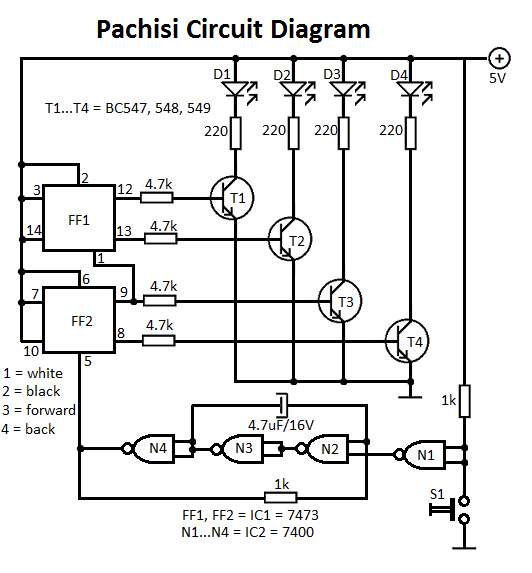
The Pachisi game is designed for two players. Each player has one figurine, which is initially placed on positions indicated by arrows on the game board. The Pachisi game, often referred to as the "Royal Game of India," is...
The count switching circuit consists of an electronic switch and a pulse delay circuit for control. The count switching circuit is designed to manage the switching of signals in a controlled manner. The electronic switch serves as the primary component...
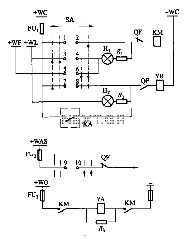
Factories and enterprises operating at voltages of 10 kV and below commonly utilize the CD10 (formerly CD2) type electromagnetic actuator as a circuit breaker. This mechanism features a mechanical anti-jump device. The control signal circuit for the CD10 actuator...