
Switching power supply Regulator 0-40V 4A by L296

The described circuit utilizes a specialized chip that features an oscillator operating at a frequency of 200 kHz. This frequency is critical for ensuring the stability and performance of the circuit. The output noise level is maintained below 1%, even under worst-case conditions, which indicates a high-quality signal output that minimizes interference and distortion.
The circuit is capable of delivering a maximum current of 4 A at an operating voltage of 20 V. This allows for a robust performance suitable for various applications requiring significant power. The voltage regulation capability extends from 0 V (true zero) to 40 V, enabling flexibility in output voltage settings, which can be crucial for applications that necessitate precise voltage levels.
Both the voltage and current limits are adjustable, providing the user with the ability to tailor the circuit's performance to meet specific requirements. This feature is particularly beneficial in applications where load conditions may vary or where specific operational parameters must be adhered to.
Attention must be given to the selection of the choke within the circuit. The ferrite material used in the choke should be rated for frequencies up to 300 kHz to ensure optimal performance and efficiency. This consideration is vital to prevent losses and maintain the integrity of the circuit's operation.
The input to the regulator is versatile, accommodating both DC and AC voltage sources, thanks to the integration of a rectifier bridge. This design choice enhances the circuit's adaptability, allowing it to function effectively in various power supply scenarios.
Overall, the circuit design emphasizes stability, performance, and flexibility, making it suitable for a wide range of electronic applications.Specificaly for the chip that is used in this circuit data are like this: Oscilator runs at freq 200kHz, output noise is below 1% (worst case), max current is 4A at 20V. Voltage can be regulated from 0, 0 V (true zero), to 40 V. Voltage and current limit, can be adjusted. You should take special care when purchasing choke. Its ferrite material shou ld be build for frequencies up to 300kHz. Input to the regulator can be DC or AC voltage becouse the input is rectifier bridge. Disclaimer All files are found using legitimate search engine techniques. This site does not and will not condone hacking into sites to create the links it list. We will and do assume that all links found on the search engines we use are obtained in a legal manner and the webmasters are aware of the links listed on the search engines. If you find a URL that belongs to you, and you did not realize that it was "open to the public", please use the report button to notify the blogmaster of your request to remove it or it will remove within 24 hours.
This is not an invitation for webblog haters to spam with requests to remove content they feel that is objectionable and or unacceptable. Proof of URL ownership is required. NOTICE: This Blog Has Already Been Reviewed And Accepted By Blogger. com 🔗 External reference
Related Circuits
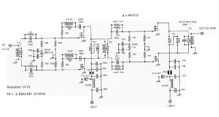
This is an RF Power Amplifier designed for low-cost QRP applications. The circuit operates over a broadband frequency range of 1.8 to 30 MHz, eliminating the need for tuning. The only adjustment required is to set the quiescent current...
The distortion produced by a typical solid-state Class-B power amplifier consists of eight mechanisms, all of which may coexist and whose distortion products overlap to create a complex result. Methods for isolating each mechanism for study and minimizing its...
This is a very useful project for anyone working in electronics. It is a versatile power supply that will solve most of the supply problems arising in the everyday work of any electronics work shop. It covers a wide...
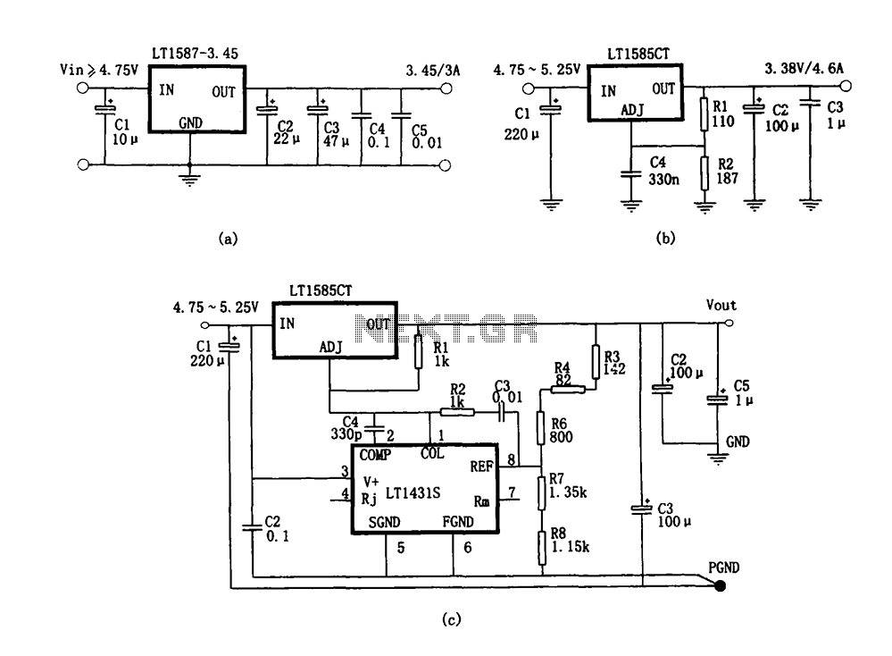
Figure (a) illustrates a microprocessor power supply circuit utilizing the LT1587-3.45. Figure (b) depicts a power supply with an adjustable output voltage constructed using the LT1585. Figure (c) showcases a computer power supply circuit formed with the LT1584 and...

Traditional soldering irons utilize mains AC supply for heating, which can be inconvenient in the absence of such a power source. This document describes a simple and cost-effective inverter circuit designed for use with standard soldering irons (25W, 30W,...
As readers may know, there are several power amplifier projects, including two that utilize integrated circuit (IC) power amplifiers, commonly referred to as power op-amps. Both of these projects have gained popularity, and this new project is not intended...