
Switching Voltage Regulators-Step up Step down and polarity invert

Switching voltage regulators are essential components in modern electronic circuits, providing efficient voltage conversion. These regulators can be categorized into three main types: step-up (boost), step-down (buck), and polarity-inverting configurations.
A step-up voltage regulator increases the input voltage to a higher output voltage. This is achieved using an inductor, switch (typically a transistor), diode, and capacitor. During the on-phase, the switch closes, allowing current to flow through the inductor, which stores energy. When the switch opens, the energy stored in the inductor is released, resulting in a higher output voltage across the load due to the inductor's tendency to maintain current flow.
Conversely, a step-down voltage regulator reduces the input voltage to a lower output voltage. This configuration also employs an inductor, switch, diode, and capacitor. When the switch is closed, the inductor stores energy. When the switch opens, the inductor discharges its energy through the load, resulting in a lower output voltage. The control mechanism in both step-up and step-down regulators is typically managed by a pulse-width modulation (PWM) technique, which adjusts the duty cycle of the switch to maintain the desired output voltage.
Polarity-inverting voltage regulators provide a negative output voltage relative to the input. This configuration utilizes a similar approach as the step-up and step-down regulators but includes additional components to invert the output. The circuit typically includes an inductor and a switch, which operates in a manner that allows the inductor to discharge in the opposite polarity when the switch is turned off.
Circuit diagrams for these configurations illustrate the interconnections between components, showcasing how energy flows through the system. Each type of regulator has its specific applications, including power supply units, battery chargers, and various electronic devices requiring stable voltage levels. Understanding the principles and design of these switching voltage regulators is crucial for optimizing performance and efficiency in electronic circuits.Switching Voltage Regulators-Step up, Step down, and polarity inverting configuration, working, and circuit diagram.. 🔗 External reference
Related Circuits
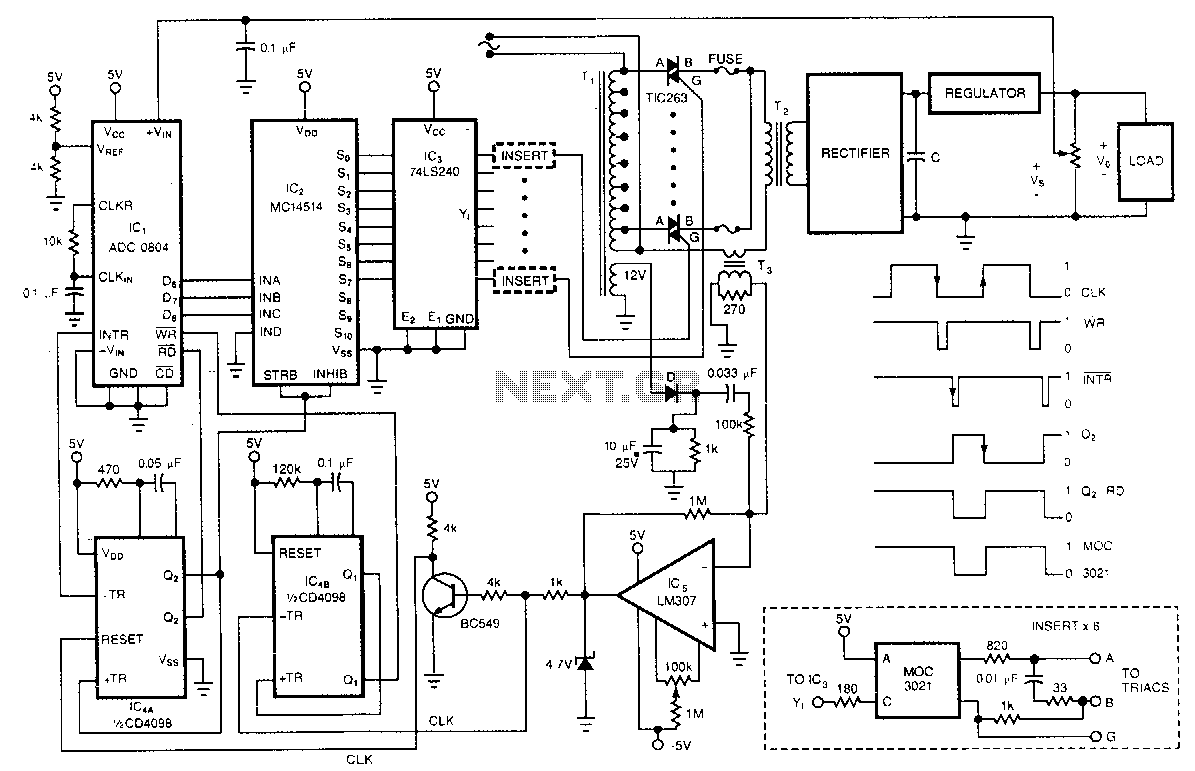
One of the control circuit's triacs selects the tap on the main transformer T1, which provides the proper preregulated voltage to the secondary regulator. T2 and its associated components comprise the secondary regulator. The ADC 0804, IC1, digitizes a...
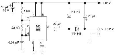
This voltage doubler circuit utilizes a 555 timer integrated circuit configured as an astable multivibrator. It can deliver a maximum output current of 50mA; exceeding this limit will result in a reduction of the output voltage. The actual output...
All miniature electronic devices operate on batteries. Some require higher than standard battery voltages for efficient operation. When a battery of the required voltage is unavailable, additional cells must be connected in series to increase the DC voltage, which...
A low voltage reference is essential for providing an offset source or biasing, or simply serving as a reference for a comparator. Its adjustable feature should be compatible with this circuit. A low voltage reference circuit is designed to deliver...
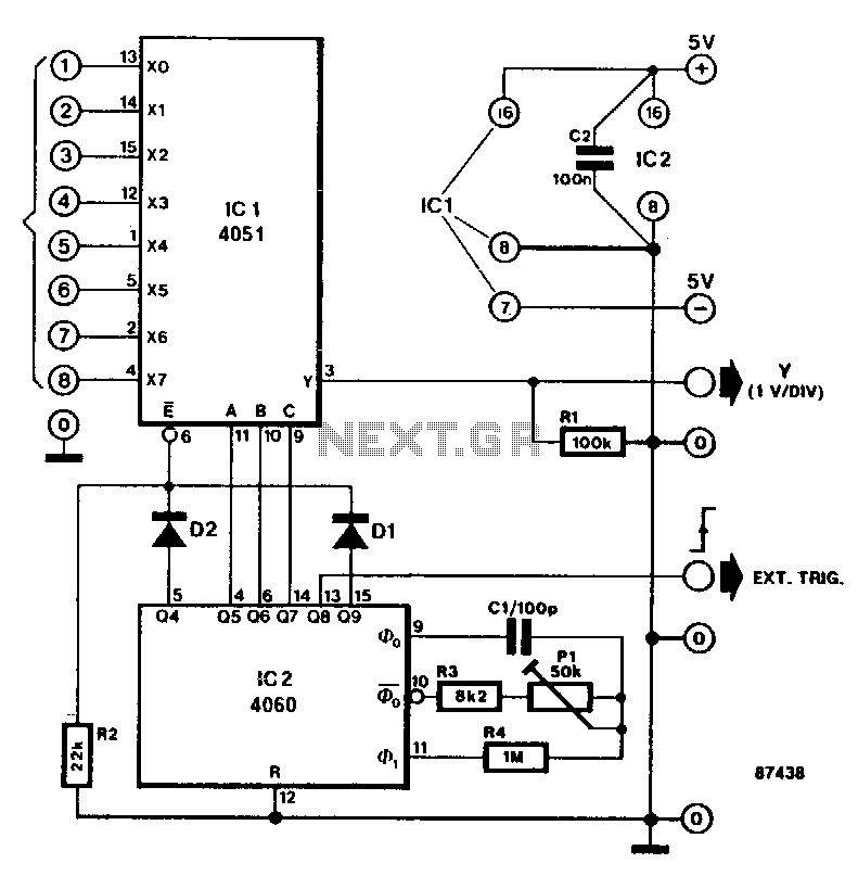
This circuit transforms a standard oscilloscope into a multifunctional eight-channel display for direct voltage measurements. The trends of each of the eight input levels can be easily monitored, although the achievable resolution is limited. The circuit diagram features an...
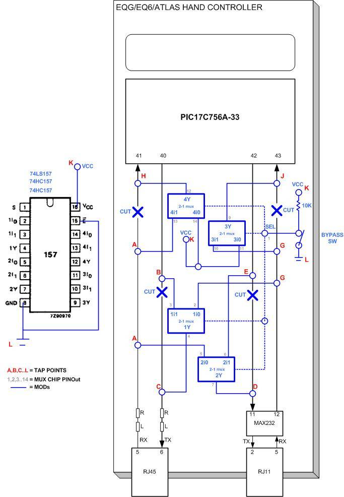
The modifications allow direct access to the stepper motor controls of the mount. Any erroneous commands or invalid data sent to the mount could inadvertently activate the stepper motors, leading to potential damage to connected equipment as the motors...