
Symmetric Output for USB Audio DAC

The described adapter circuit facilitates the integration of a USB Audio DAC with professional audio equipment by altering the output configuration. The modification enhances compatibility with XLR inputs, which are standard in professional audio systems.
To implement the modification, the following steps should be taken:
1. Identify the output resistors R11 and R12 on the printed circuit board of the USB Audio DAC. R11 is the resistor that needs to be replaced, while R12 will be modified to accommodate the new resistor R11a.
2. Carefully desolder R11 from the circuit and replace it with a 68-ohm resistor, labeled R11a. This change reduces the output impedance, improving the DAC's ability to drive professional audio equipment.
3. Unsolder R12 and connect the newly introduced resistor R11a in series with it. This series connection is crucial as it allows the junction point between R11a and R12 to serve as the signal return connection for pin 3 of the XLR socket.
4. The same procedure must be replicated for the right audio channel, where the resistors R16, R16a, and R17 are located. This ensures that both left and right channels are configured for pseudo-symmetric output.
5. After completing the modifications, thorough testing should be conducted to ensure that the DAC functions correctly with the connected professional equipment, confirming that the output is indeed pseudo-symmetric and meets the desired audio quality standards.
This modification significantly enhances the versatility of the USB Audio DAC, allowing it to interface seamlessly with high-end audio systems, thereby improving the overall audio experience.This simple adapter circuit is specially intended for use with the USB Audio DAC published in this website elsewhere. With an easily implemented modification, it is possible to make the output of the D/A converter pseudo-symmetric, so that it can be connected to professional equipment having XLR line inputs.
This will do even more justice to the h igh quality of the USB Audio DAC. The modification actually amounts to just adding a single resistor (R11a) and changing the value of the existing resistor at the output of the audio DAC (R11) from 100 to 68. Components C14 and R12 remain unchanged. It is not difficult to make this change on the printed circuit board of the audio DAC, but a bit of improvisation is necessary.
After replacing R11 with a 68- version, unsolder R12 and connect R11a in series with it. Bring out the junction of these two resistors to act as the signal return connection (pin 3 of the XLR socket). The same operation must also be carried out on the right channel, where the affected resistors are labelled R16, R16a and R17.
🔗 External reference
Related Circuits
You can use this powerful amplifier in any small audio project. It is very small (6.5 x 4.5 cm). It outputs 10W and uses a 9V battery. More: Components List R1: 6 Ohm R2: 220 Ohm R3: nothing R4:...
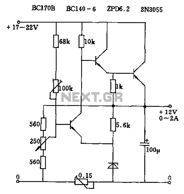
The circuit output voltage can be continuously adjusted from zero to its maximum value. The baseline is established by a constant current sourced from the auxiliary power supply circuit. The reference current of 500 microamperes can be fine-tuned to...
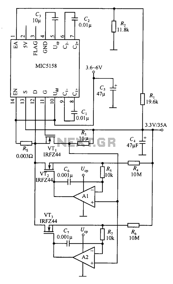
The MIC5158 is designed to manage tasks by controlling multiple external N-channel MOSFETs in parallel, which enables high current or high power output for a linear regulator circuit. This is illustrated in the accompanying figure. The operational amplifier circuit...
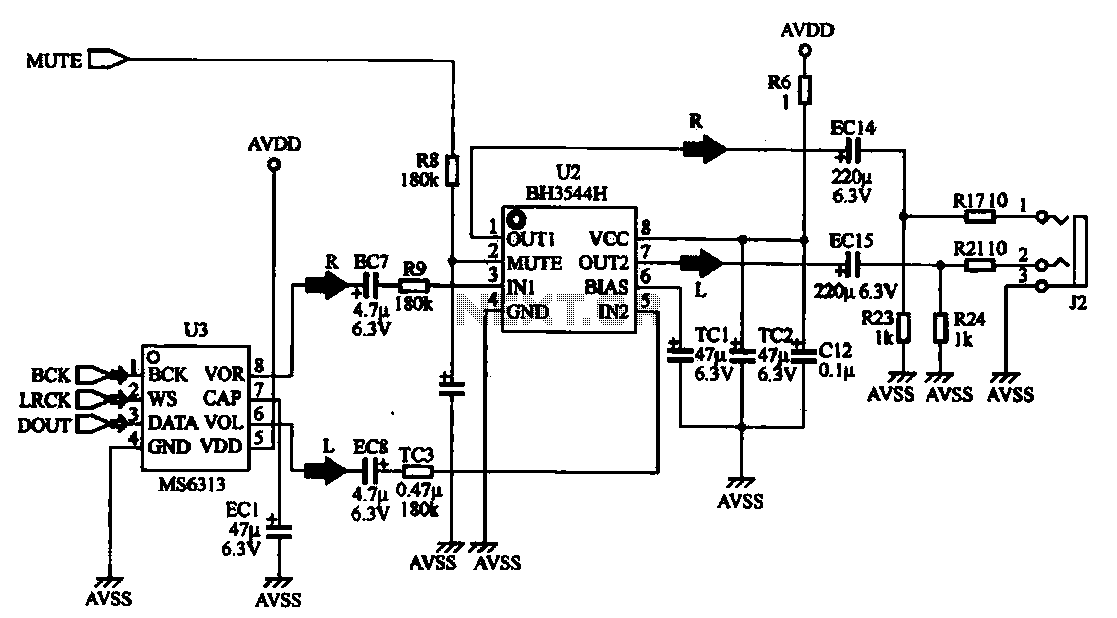
The MP4 audio circuitry consists of audio D/A converters and an audio amplifier combination circuit. This design features a straightforward circuit layout, making it suitable for integration into compact MP4 digital devices. The MP4 audio circuitry is designed to efficiently...
This design is based on an 18 Watt audio amplifier and was developed primarily to meet the needs of users who are unable to find the TLE2141C chip. It utilizes the widely available NE5532 dual integrated circuit; however, its...
The standard Class AB audio power amplifier allows for direct coupling of the amplifier's output to speakers. This is beneficial as it eliminates capacitors or transformers that could compromise sound quality. The speakers are connected directly to the amplifying...