
symmetrical preamplifier class a

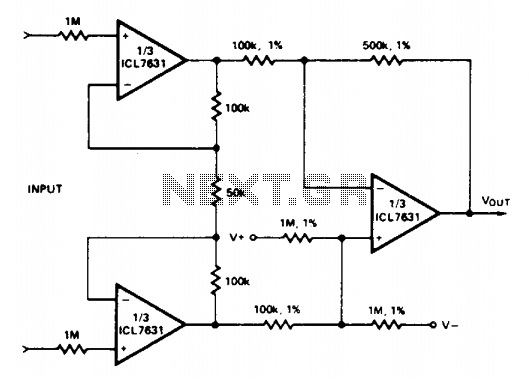
The symmetrical amplification unit circuit is designed to achieve high fidelity and low distortion in audio applications. The use of a differential amplifier at the input stage allows for the rejection of common-mode signals, enhancing the circuit's ability to amplify only the desired signals. Selecting the right FET transistor is crucial, as it influences the circuit's transconductance and overall gain characteristics.
The circuit's architecture includes a current mirror stage on both sides, which plays a vital role in maintaining balance and stability within the amplifier. This configuration ensures that the output currents are mirrored accurately, allowing for improved linearity and reduced distortion. The current mirror also helps in minimizing the effects of variations in transistor characteristics, thus enhancing the circuit's performance.
Furthermore, the reduction of overall negative feedback is a significant design consideration. While negative feedback is typically employed to improve linearity and bandwidth, excessive feedback can lead to instability and oscillations. By carefully designing the feedback network, this circuit achieves a desirable balance between stability and performance, resulting in a more robust amplification characteristic.
In summary, this symmetrical amplification unit circuit, inspired by Lisley Hood's design, incorporates a differential amplifier with a carefully selected FET transistor and a balanced current mirror stage. These design choices contribute to its effectiveness in audio amplification, ensuring high performance while minimizing distortion and feedback-related issues.This is a symmetrical amplification unit circuit, more composed, modified by a construction which was proposed some years ago by Lisley Hood. The most important reason is to get the right transistor FET at differential amplifier at input. In spite of all this it is a circuit which provides, current mirror stage of both sides, with the result of lessening the overall negative feedback..
🔗 External reference
Related Circuits
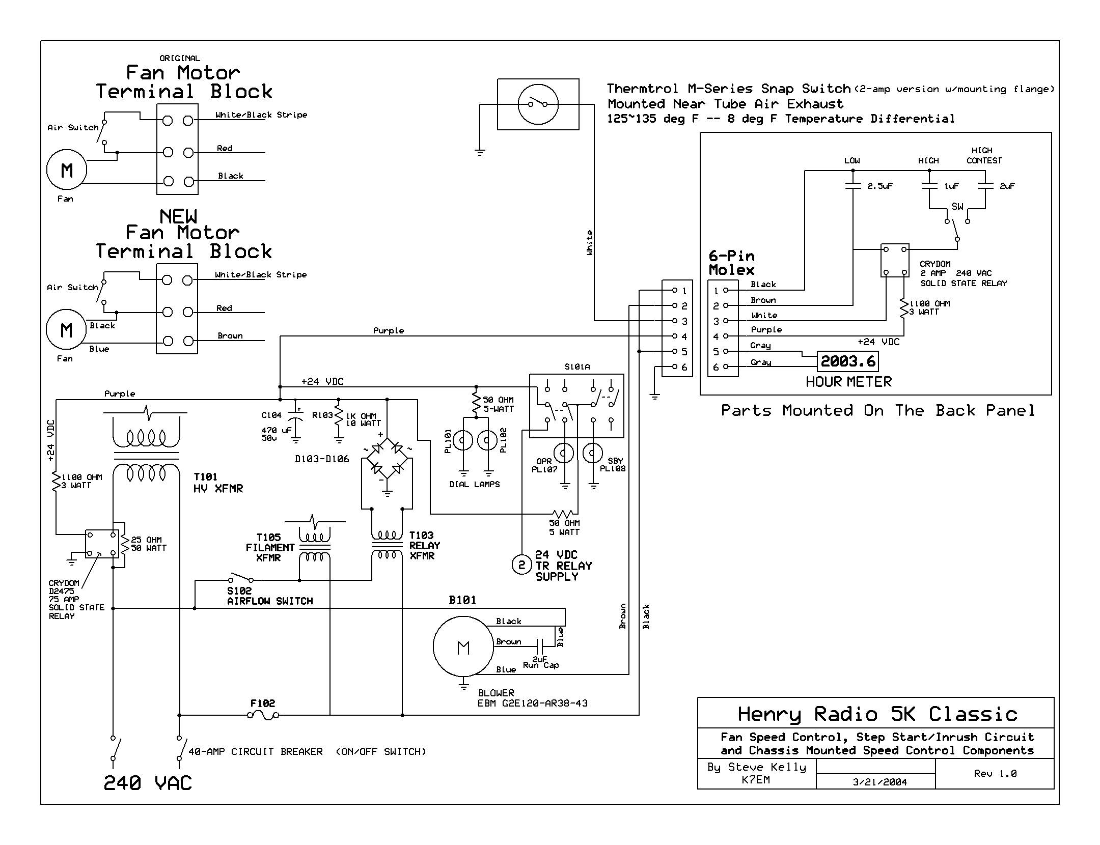
The back cover has been removed, revealing the upper deck of the power supplies and the original Dayton 2C915A blower (220VAC - 140CFM) mounted to the cabinet's underside. The RF deck enclosure has also been taken off. The upper...
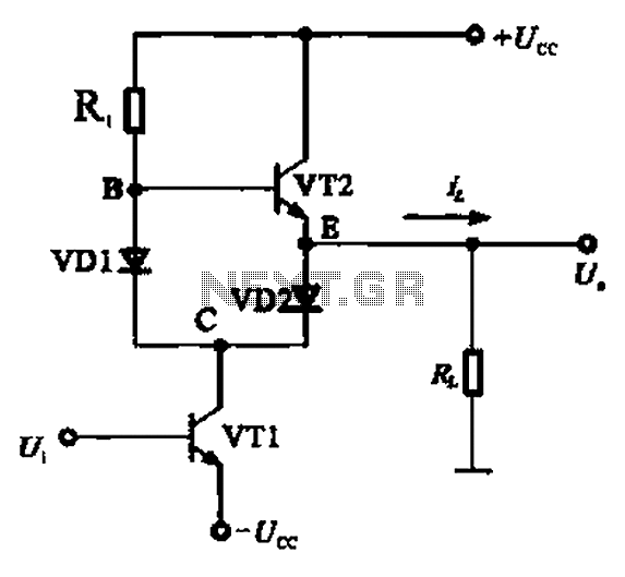
A Class AB output stage circuit is coupled with diodes, as illustrated in Figure 10-8. The static bias circuit for transistor VT1 (not shown) is adjusted so that the output at point E is at ground DC voltage UE....
The Audio Research Corporation LS22 Line Stage Preamplifier was selected for this upgrade. The Audio Research LS22 Line Stage Preamplifier is a high-performance audio component designed to enhance the quality of sound reproduction in audio systems. This preamplifier features a...
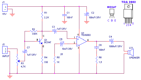
A small amplifier with nice characteristics: Tendency of catering: 15V. Force of expense: 4.2Wrms in the 4W. Minimal signal of entry: 94mVp-p with preamplifier, 0.65Vp-p without the preamplifier. More: Materially: R1=2.2kΩ R2=330kΩ R3=4.7kΩ logarithmic potentiometer R4=330Ω R5=1kΩ R6=1.5Ω C1,...
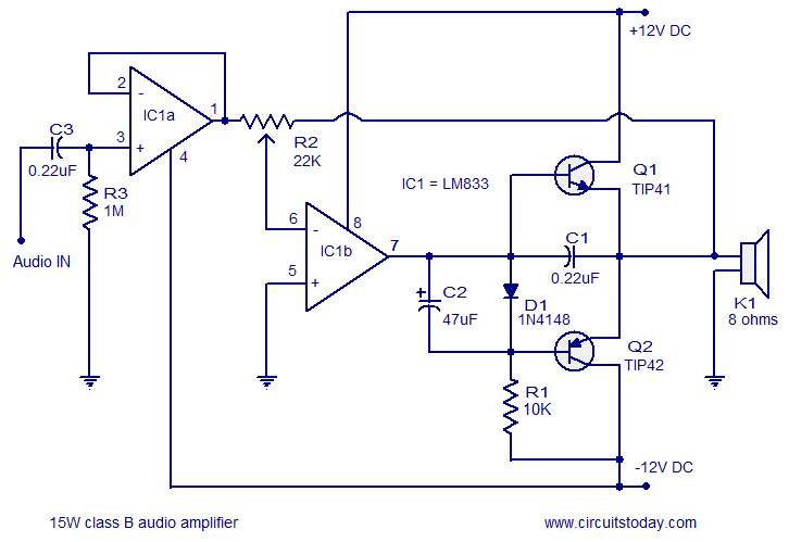
A 15 Watts Class B audio amplifier circuit is designed using a dual op-amp LM833. The schematic diagram is provided, and a potentiometer allows for volume control. The 15 Watts Class B audio amplifier circuit utilizes the LM833 dual operational...
Input current (from sensors connected to the patient) is limited to less than 5 µA under fault conditions. Note that Avol = 25 single Ni-cad battery operation. The circuit is designed to ensure that the input current from patient-connected sensors...