
Synchronizing Multiple High-Speed Multiplexed DACs for Transmit Applications

This document outlines the techniques and methodologies for synchronizing multiple high-speed Digital-to-Analog Converters (DACs) in various transmitter applications. Synchronization is crucial in systems where multiple DACs are used to ensure that the signal outputs are coherent and aligned in time, which is essential for maintaining signal integrity and performance.
The synchronization process typically involves the use of a common clock signal distributed to all DACs to ensure that they operate in unison. This can be achieved through various methods, including the use of phase-locked loops (PLLs) to generate a stable clock signal, or by utilizing a master-slave configuration where one DAC acts as the master clock source for the others.
In addition to clock synchronization, the application note may also cover techniques for managing data alignment between the DACs. This can involve buffering data streams to ensure that they are processed simultaneously, thereby preventing any potential delays that could lead to phase discrepancies in the output signals.
Furthermore, the document may discuss the importance of considering the layout and design of the PCB when implementing multiple DACs. Proper grounding, power distribution, and signal routing are critical to minimize noise and interference, which can adversely affect the performance of the synchronized DACs.
The application note serves as a valuable resource for engineers and designers working with high-speed DACs in transmitter applications, providing practical guidance on achieving effective synchronization to enhance overall system performance.This application note provides insight into how synchronize multiple multiplext high-speed DACs in transmitter applications.. 🔗 External reference
Related Circuits
This is a long-range stable FM transmitter circuit. The circuit utilizes an LM2950 5V voltage regulator IC in a TO-92 transistor package, which provides a stable 5V to the oscillator until the 9V battery voltage drops to 5.5 volts,...
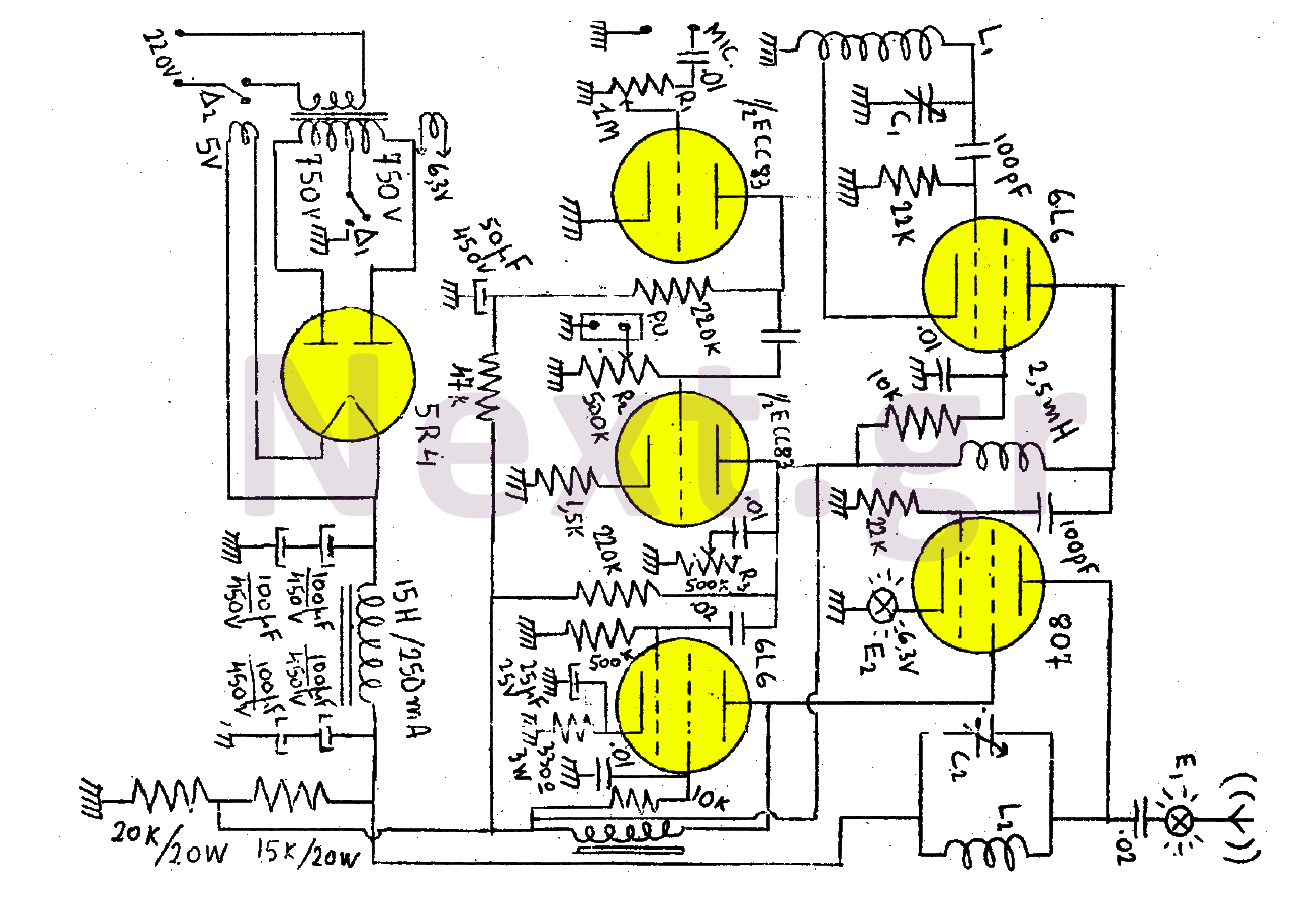
This transmitter consists of a total of five bulbs. The 6L6 tube functions as an oscillator, directing oscillations to the grid of the 807 tube, which serves as the final amplifier and the transmitter output lamp. The amplifier includes...
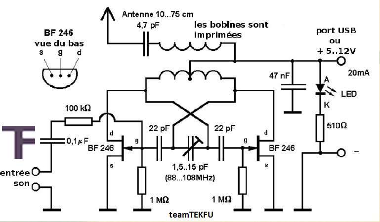
This compact FM transmitter has a range of approximately 50 meters and is designed for connection to a USB port. By utilizing multiple mini-transmitters, a comprehensive and engaging radio program can be created. The power supply through the USB...
This project is straightforward to construct and will transmit high-quality sound within the FM band (88-108 MHz). An important component is that the... This project involves the design and construction of a simple FM transmitter capable of broadcasting audio signals...
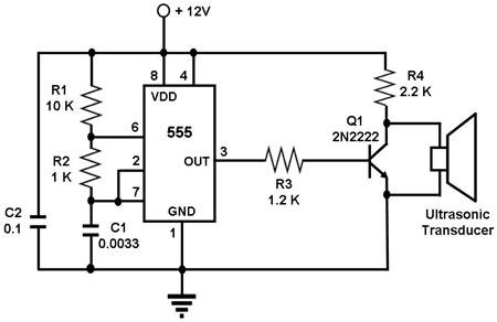
The circuit utilizes a 555 timer integrated circuit (IC) configured as an astable multivibrator, which generates a continuous signal at a specific frequency as long as its reset pin (pin 4) is held high. The ultrasonic transducer employed in...
This 2-meter 144 MHz fox hunt transmitter is utilized in amateur competitions where participants seek to locate a concealed transmitter using primarily homebrewed receivers. The 144 MHz fox hunt transmitter is designed for use in amateur radio competitions, commonly referred...