
long range stable fm transmitter

The long-range FM transmitter circuit is designed for reliable and stable performance, utilizing the LM2950 voltage regulator to maintain a consistent voltage supply essential for oscillator stability. The choice of the TO-92 package for the LM2950 allows for compact integration into the circuit, minimizing space and enhancing portability.
Transistor Q1 serves as the oscillator, generating the modulated signal for transmission. The stability of the oscillator is critical as it directly affects the quality of the transmitted signal. Q2, acting as an RF amplifier, boosts the output signal strength, ensuring that the transmitted signal can cover a significant distance. The separation of the oscillator from the antenna by Q2 is a vital design feature that mitigates potential feedback issues, thus enhancing the overall frequency stability of the transmitter.
The air-cored coils L1 and L2, with their specific winding configuration, play a crucial role in determining the frequency of operation and the efficiency of the transmission. The use of 1mm enameled wire for the coils contributes to reduced losses and improved performance. The adjustment capabilities provided by trimmer capacitors C4 and C5 allow for fine-tuning of the transmitter's operating frequency and output power, respectively, which is essential for achieving optimal performance in various operating conditions.
To effectively measure and adjust the output power, the inclusion of a field strength meter or RF power meter is recommended. This ensures that the transmitter can be calibrated for maximum efficiency and range. The suggested 30-inch wire antenna is designed to provide the best possible range and signal clarity, making it an essential component of the overall design.
Maintaining close proximity of all components within the circuit layout is crucial for minimizing interference and ensuring stable operation. The expected operational range of 2 kilometers or more in open areas highlights the effectiveness of this design in achieving long-range FM transmission capabilities. Overall, this circuit represents a well-engineered solution for those requiring a stable and reliable FM transmitter.This is a long range stable FM transmitter circuit. The circuit is using a LM2950 5V voltage regulator IC comes in TO 92 transistor package, which will provide a stable 5V to the oscillator till the 9V battery runs down to 5. 5 volts, due to which the oscillator becomes frequency stable. The circuit is using two transistors, transistor Q1 is workin g as an oscillator and Q2 is working as an RF amplifier and also separating the oscillator from the antenna due to which the circuit becomes more frequency stable. Coil L1 and L2 are air cored coils equal to 10 turns of 1mm enameled wire close wound on a 3mm form. The frequency of the transmitter can be adjusted with trimmer C4. The maximum output power can be achieved by adjusting the trimmer C5. A field strength meter or RF power meter will be required to set the transmitter on the maximum output power.
Use 30 inch wire antenna for maximum range. Keep all the components as near as possible in the circuit. The maximum range of the circuit will be 2 KM or more in the open area. 🔗 External reference
Related Circuits
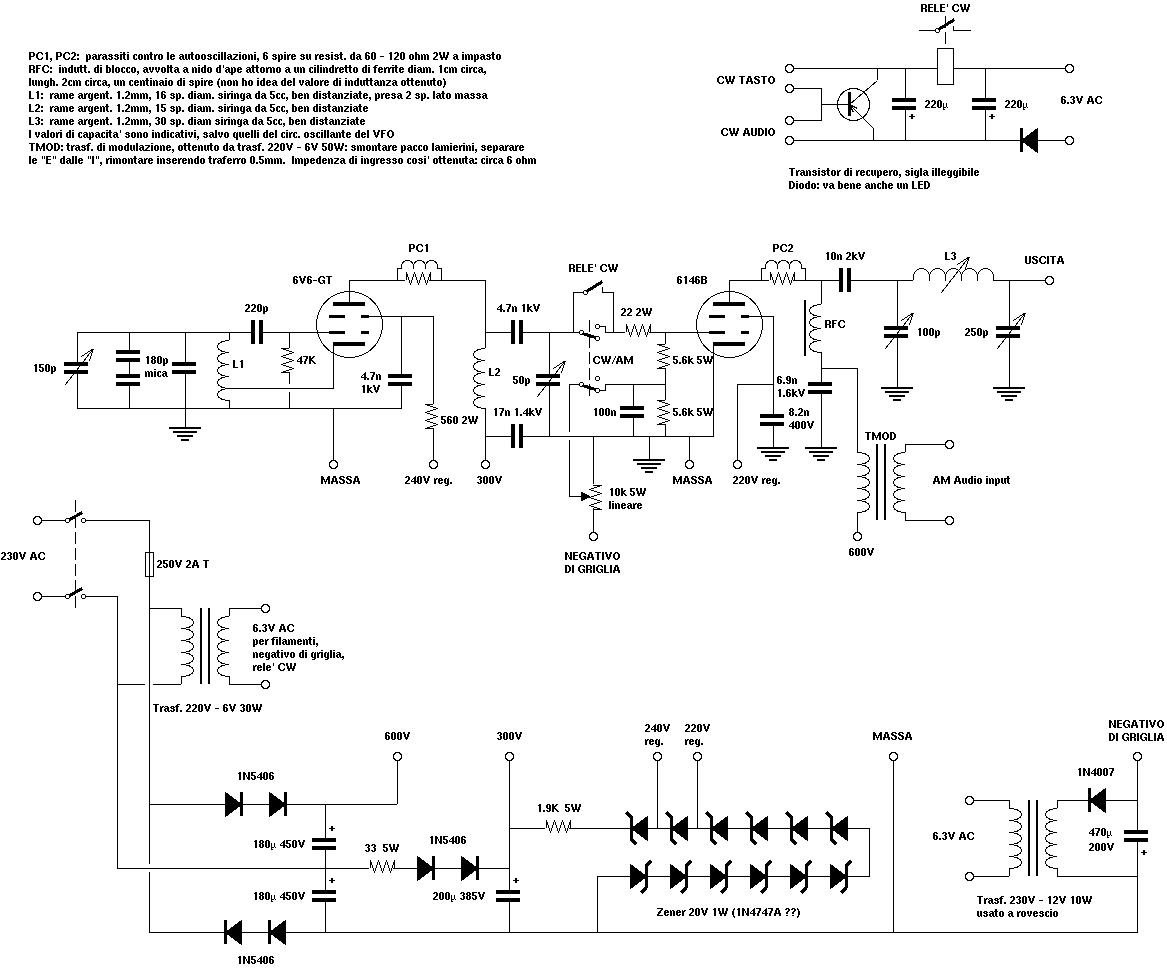
A copy from an old Italian magazine of amateur electronics proposed an add-on for tube receivers. The add-on was a simple one-tube short-wave transmitter leveraging the same power supply already available in the receiver. The project reported in that...
This is a variation of the Electron Coupled Oscillator (ECO) circuit, pioneered by Dow in 1931. Dow's ECO has the screen grounded for RF. In this circuit, filament-type tubes are used instead of heater-cathode types, eliminating the need for...
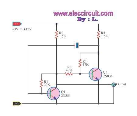
An oscillator circuit of this nature is often utilized as a clock circuit. This circuit employs a crystal frequency control with a stability of one million hertz. An oscillator circuit designed for clock applications typically generates a periodic signal, which...
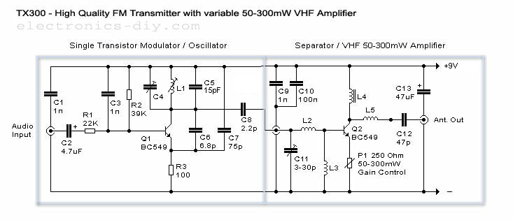
50-300mW FM Transmitter with TX300 Electronic Circuit Schematic Wiring Diagram. The FM transmitter circuit is designed to operate within a power range of 50 to 300 milliwatts, making it suitable for various applications such as amateur radio broadcasting and low-power...
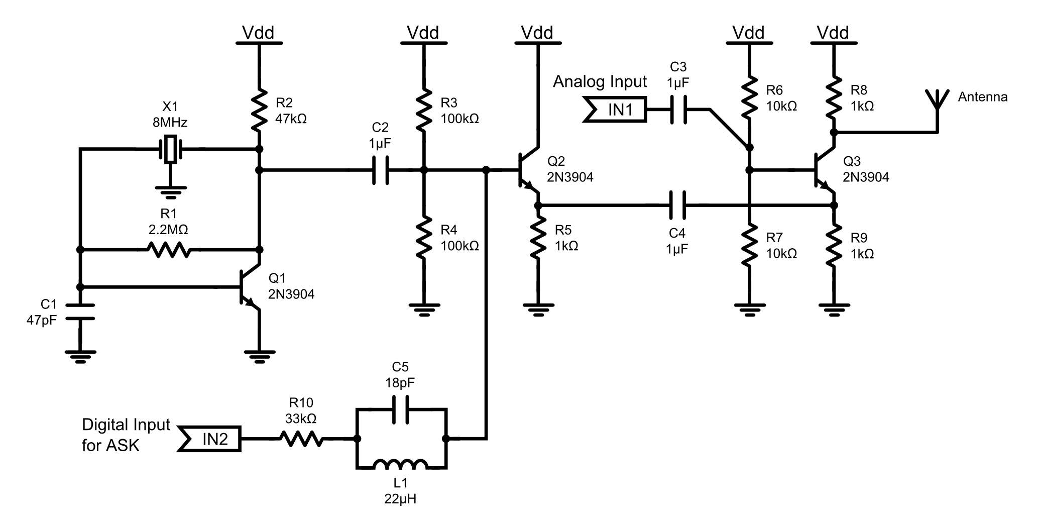
This is an 8MHz amplitude modulated (AM) radio transmitter designed primarily for work purposes and as an exercise in electronics. It serves as a simple radio transceiver that may be utilized for various future projects. The 8MHz AM radio transmitter...
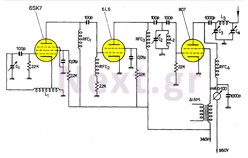
This transmitter operates in the shortwave range from 6 MHz to 22 MHz. Coil L1 serves as the shortwave oscillating coil for the 6SA7 vacuum tube and is commercially available. Capacitor C1 is a variable capacitor with a capacitance...