
synth mg
The analog synthesizer's architecture is fundamentally based on several interconnected building blocks, each serving a specific function. The voltage-controlled oscillator (VCO) generates audio signals, which can be modulated by varying the control voltage. This modulation can be achieved through various methods, such as using low-frequency oscillators (LFOs) or envelope generators that respond to user input or programmed sequences.
The voltage-controlled filter (VCF) shapes the harmonic content of the audio signal produced by the VCO. By adjusting the control voltage, the filter can alter its cutoff frequency and resonance, allowing for a wide range of tonal possibilities. The variable gain amplifier (VCA) further modifies the amplitude of the signal, enabling dynamic control over the output level in response to user-defined envelopes or modulation sources.
The envelope generator (EG) plays a critical role in shaping the amplitude contour of the sound, providing parameters such as attack, decay, sustain, and release (ADSR). This allows musicians to create expressive sounds that evolve over time. Control interfaces, including keyboards and modulation wheels, facilitate user interaction, enabling real-time manipulation of parameters and enhancing the performance experience.
The integration of these components requires careful consideration of circuit design to ensure stability, low noise, and high fidelity. The design process may involve the use of operational amplifiers, transistors, and other analog devices to achieve the desired performance characteristics. Additionally, the ability to program and recall patches is a significant advancement that enhances usability and creativity in sound design.
Overall, the synthesis process is a complex interplay of electrical signals and control voltages, resulting in a rich tapestry of sounds that can be tailored to suit a wide range of musical styles and preferences. The continued interest in analog synthesizers underscores their unique sonic qualities and the creative possibilities they offer to musicians and sound designers.There are various approaches to analog synthesizer building, luckily they don`t vary too much in terms of the applied building blocks. The main building blocks are: oscilator (VCO), filter(VCF), variable gain amplifier (VCA), envelope generator (EG), and controls such as a keyboard and modulation and pitchbend wheels.
VC is short for `Voltage Controlled`, it means that the main characteristics of the block are adjustable by appying a voltage at some input, for instance to change the pitch of an oscilator, or the gain of an amplifier. The amount of parameter change is often standardized, such as +1 Volt per (higher) octave for pitch. Implementing the various building blocks as analog parts, such as in the earlier synths, is not an ovious task, since the demands on the circuits are that they cover fairly large parameter ranges, are stable (over time and temperature), have good audio quality or attractiv synthesis properties, and preferably would be programmable and yield well-repeatable patches.
All but the latter two demands are in some way fulfilled by the circuits various manufacturers have put out, and it is an interesting phenomenon that various imperfections of relatively old circuits are actually making some of these designs musically attractive. This can be exemplified by the fact that various old analog synthesizers are sold for prices not too far from modern counterparts, and at significant fractions of their original price.
Bob Moog is one of the main innovators in the (at that time mainly analog) sound synthesis area. His synths are famous for their fat and clear sounds, and contained innovative circuitry that can produce sounds that are still very popular, for instance in contemporary house music. At the risk of infringing on some copyrights, I`ve looked at some of the service book circuit diagrams, and reproduced parts of the original circuitry with parts that should be readily available (and happened to be available in Microsim`s Pspice Simulator).
They are not exactly the original, but functionally there is hardly a difference for the greater part. The oscilator is composed of a current source linearly sinking a capacitor`s voltage, a schmitt-trigger-ed comparator detecting the zero crossing, and a field effect transistor to shortcircuit the capacitor to its initial discharged state.
The feedback circuitry of the schmitt-trigger makes it produce a 300nS discharge pulse which is sufficient to discharge the capacitor and to compensate for the overshoot caused by the charge injected into the fet`s gate to make it switch fast (It tranfers hundreds of mAmps peek current). The idea of the original circuit is that the discharge phase should take under 500 micro seconds, so the effect of the (fixed) discharge time on the frequency dependency of the oscilator on the drive current is less than one tenth of a percent for the highest frequency, 20kHz.
This circuit is a bit faster, but it does suffer from a touch of overshoot, that is the voltage is not exactly put at 5. 00 Volt. Then again, the amount of overshoot is fixed, and I haven`t found a spice model for the fet (and comparator) used in the original cicruit.
From the following diagram it can be seen that the circuit oscillates fine at in this case ca 14kHz. This frequency can be determined by the current source at the bottom, which is a part of the original circuit, and contains an exponential convertion, that is, the input voltage is exponentially resonsible for the capacitors charge current. From the charge current, the frequency can easily be derive, considering the Voltage drop of the downward sawtooth is constant and ca.
5. 0 volt. The following diagram shows a blowup of the `reset` time or dischage time of the capacitor 🔗 External reference
Related Circuits
The circuit consists of two twin-T oscillators set below the oscillation threshold. To initiate oscillation, a touch on the Touch Pad is required. The schematic diagram illustrates the circuit, where different touch patterns on the pads can create a...
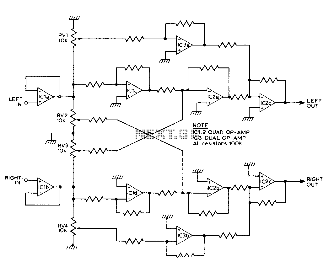
This circuit synthesizes two rear channels for quadraphonic sound when provided with a stereo signal. The rear output for the left channel is created by combining the left channel input, which is 180 degrees out of phase, with a...
The core of this drum machine is based on an electronic drum stick. Swinging the stick produces drum sounds, specifically three sounds: snare, bass drum, and hi-hat. When the stick is swung, it plays a snare sound. There are...
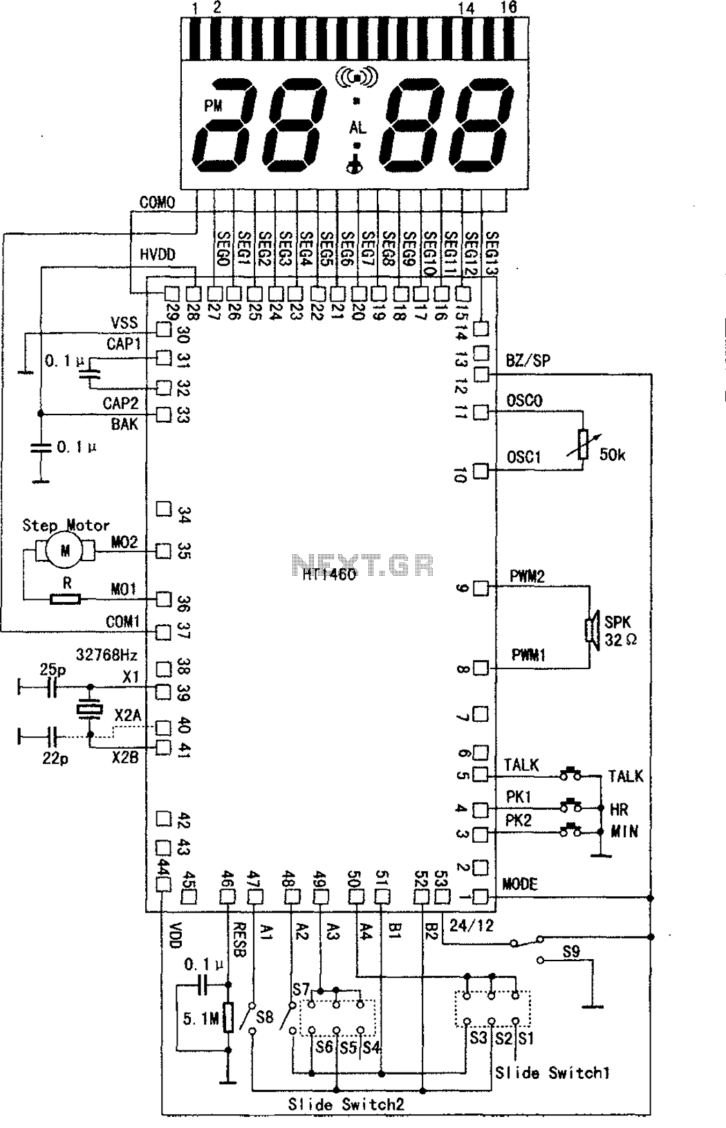
The speech synthesis circuit incorporates a microprocessor series, LCD drivers, a clock oscillator, input and output ports, memory, and a multi-voice audio signal amplifier circuit unit. This series circuit is primarily utilized in voice clocks, thermometers, electronic calendars, and...
This is a programmable frequency multiplier that typically utilizes digital logic integrated circuits. The synthesizer is designed to multiply a reference frequency by a programmable factor to achieve virtually any desired frequency. For instance, with a reference frequency of...
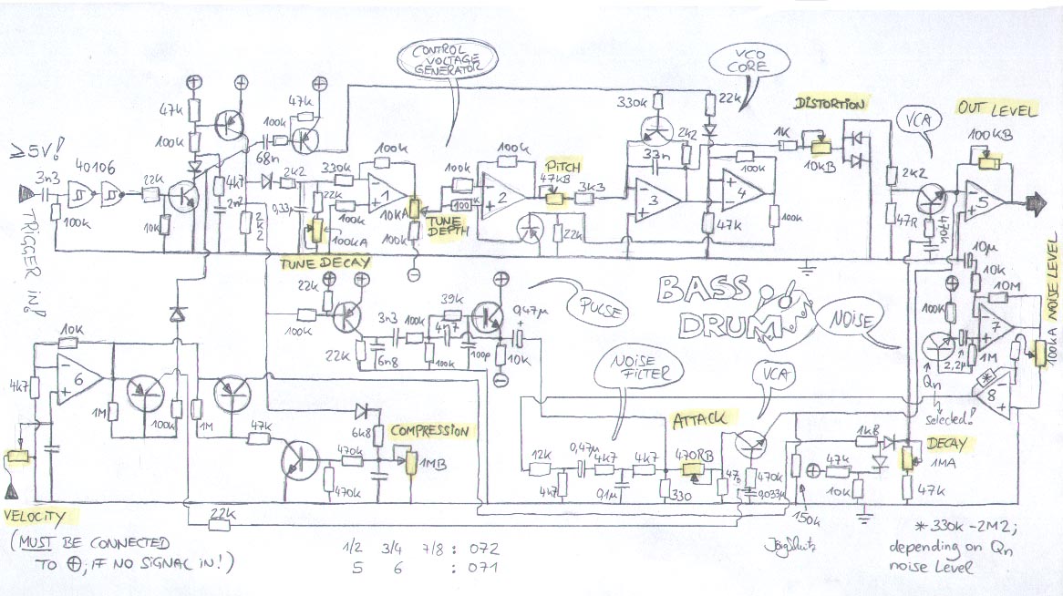
This PCB design was inspired by Colin Fraser, who discovered valuable enhancements to the bass drum circuit of the Roland TR909. The project by Trevor Page, known as the 9090 project, also provided significant assistance. As an enhancement to...