
SYSTEM A MODULATOR

The vision modulator circuit is illustrated in Fig. 1. The 1V peak-to-peak video input is first amplified by transistor Tr1/2 and subsequently fed through emitter-follower transistor Tr3 to the DC restorer Tr4. Transistor Tr5 is configured in a Butler oscillator circuit operating at 45 MHz. The output from the modulator chip is transformer coupled to the output socket via a 10 dB pad and a 6 dB combining network. The 10 dB pads in both the vision and sound modulator circuits serve as isolators to protect each modulator from the other's RF output. The sound modulator circuit (refer to Fig. 2) is analogous, with IC2 driving the modulator chip in a push-pull configuration to minimize distortion. The audio sensitivity of 1V RMS = 100 percent modulation is determined by the value of resistor R1, which can be adjusted as needed. For instance, with R1 set at 100 kΩ, 100 percent modulation is achieved with a 200 mV RMS input; with R1 at 1 MΩ, 2V RMS equals 100 percent modulation. The quiescent carrier level is established by two biasing networks connected to the audio input pins 1 and 4 of the MC1496. Both modulators generate 800 mV of RF across the secondary windings of the output transformers T2 and T4 under maximum modulation conditions (peak white for video and the positive peak of a 1V sine wave for audio). Each modulator produces approximately 130 mV of RF at the output socket, necessitating about 20 dB of additional attenuation when connected directly to the aerial socket of a set. This configuration allows several sets to be driven via a passive splitter network if desired.
It is noteworthy that the peak vision to average sound power ratio is 6 dB (4:1) instead of the correct 7 dB (5:1). However, this has not caused issues with any set utilized, though purists may opt to increase the loss in the sound modulator's output pad from 10 dB to 11 dB if preferred. The prototype was constructed on a single Veroboard Eurocard with a "colander" ground plane. Alternatively, a "solid construction" approach may be employed using a plain copper-clad board measuring about 4 x 6 inches, preferably made of fiberglass. The construction process begins with fixing the coil formers to the copper side of the board, followed by gluing the MC1496 integrated circuits upside down. All wire-ended components can then be soldered directly to the corresponding IC pins. A small soldering iron and a steady hand are essential for this task. The video amplifier/DC restorer and the audio amplifier can be assembled on a small piece of Veroboard, which is then mounted on the main board. The specific types of transistors are not critical; the selected components were used because they were readily available. Any RF types are suitable for the oscillators, while small-signal silicon general-purpose types are appropriate for the video section. Non-electrolytic capacitors should be miniature ceramic types, and polarized capacitors should be either tantalum or low-leakage electrolytics. Resistors should be 0.25W, 5 percent carbon or metal film types, and the crystals were custom-made by IQD Electronics.With the impending close down of the 405-line transmitter network those of us with collections of early TV sets are having to make new arrangements to supply them with suitable signals. Whatever the scheme used, some method of converting baseband audio and video into a form suitable for feeding into the set`s aerial socket is required.
The modulat or described in this article was designed to perform this task with little degradation of the signal. Separate carrier generators and modulators are used for the sound and vision for best possible sound-on-vision and vision-on-sound performance.
Crystal control of the oscillators was chosen to ensure stability and reduce alignment problems. The choice of Channel 1 (41. 5MHz sound, 45MHz vision) was made because the vast majority of 405-line TV sets, including all pre-war models, can operate on this channel. Those with one of the few Ch. 4 "Birmingham" models of the late 40s should be able to modify the design for 58. 25MHz sound and 61. 75MHz vision without much difficulty. Fig. 1 shows the vision modulator circuit. The 1V peak-to-peak video input is first amplified by Trl/2 and then fed via the emitter-follower Tr3 to the d.
c. restorer Tr4. Tr5 is connected in a Butler oscillator circuit operating at 45MHz. The output from the modulator chip is transformer coupled to the output socket via a lOdB pad and a 6dB combining network. The lOdB pads in this and the sound modulator circuit act as isolators to protect each modulator from the other`s r.
f. output. The sound modulator circuit (see Fig. 2) is similar, with IC2 driving the modulator chip in push-pull to reduce distortion to a minimum. The audio sensitivity of 1V r. m. s. = 100 per cent modulation is set by the value of Rl, which can be varied if desired. For example, with Rl at lOOKohm 100 per cent modulation is achieved with a 200mV r. m. s. input; with Rl at 1Mohm 2V r. m. s. equals 100 per cent modulation. The quiescent carrier level is set by the two biasing networks connected to the audio input pins 1 and 4 of theMC1496. Both modulators generate 8OOmV of r. f. across the secondary windings of the output transformers T2 and T4 under maximum modulation conditions (peak white for video and the positive peak of a 1V sinewave for audio).
Each modulator thus produces about 130mV of r. f. at the output socket, so about 20dB of extra attenuation will be needed when this is connected directly to the aerial socket of a set. This allows several sets to be driven via a passive splitter network if required. It will be noticed from the above that the peak vision to average sound power ratio is 6dB (4:1) rather than the correct 7dB (5:1).
This has never caused problems with any set I`ve used, but purists may if they wish increase the loss in the sound modulator`s output pad from lOdB to lldB. The prototype was constructed on a single Veroboard Eurocard with a "colander" ground plane. An alternative would be to use "solid construction" on a piece of plain copperclad board about 4 x 6in.
, preferably glassfibre. Start by fixing the coil formers to the copper side of the board, then glue the MC1496s to the board upside down. All the wire-ended components can then be soldered directly to the appro- priate i. c. pins. A small soldering iron and a steady hand are essential. The video amplifier/d. c. restorer and the audio amplifier can be built on a small piece of Veroboard which is then mounted on the main board.
The transistor types are not critical. I used those specified because they were to hand. Any r. f. types should be suitable for the oscillators and any small-signal silicon general-purpose types for the video section. The non-electrolytic capacitors are all miniature ceramic types and the polarised capacitors bead tantalum or low-leakage electrolytics.
The resistors are 0. 25W, 5 per cent carbon or metal film types and the crystals were made to order by IQD Electronics. Th 🔗 External reference
Related Circuits
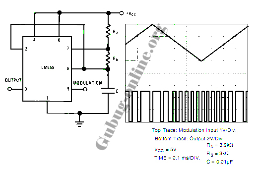
This design circuit for a pulse position modulator can be easily constructed using a 555 integrated circuit (IC). The pulse position modulator modulates the on-period while maintaining a fixed off-period. The circuit utilizes the 555 timer IC in astable mode...
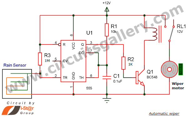
Have you seen Audi, Lexus, or Ford rain-sensing wipers and wondered how they operate in these vehicles? They are controlled by sensors located at the center of the windscreen, which detect raindrops and activate the wiper motor. The functioning...
The typical home solar power system primarily comprises a roof-mounted solar panel, a charge controller, and a storage battery bank, along with direct or electric connections. A home solar power system is designed to harness solar energy for residential use,...
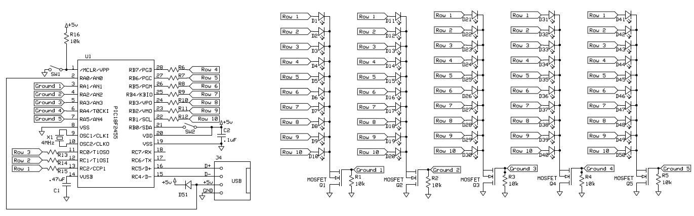
To control 40 LEDs using a single PIC 18F2455 microcontroller, the LEDs were organized into a configuration of four columns, each containing 10 rows of LEDs. Each LED in a column was connected to a separate pin on the...
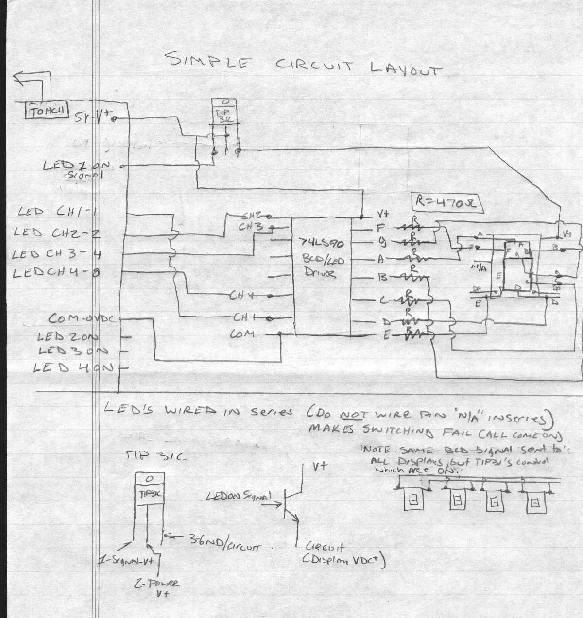
This system is a drag race timing system centered around a microcontroller. It includes a Christmas Tree (comprising three yellow, one green, and one red light), a fault sensor (which checks if a racer starts before the green light),...
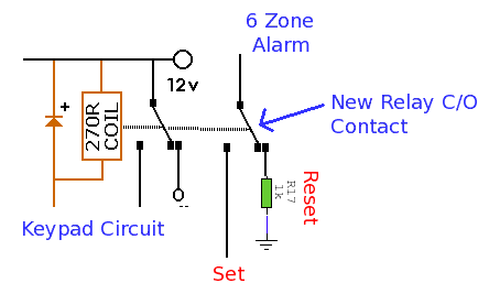
This alarm system features six independent zones, one timed entry/exit zone, a seven-segment LED display, and a test or walkthrough capability. It is designed for use in small office or home environments and can be adapted to utilize a...