
Siren Circuits using timer 555

The three siren circuits utilize the versatile 555 timer IC to create distinct auditory signals representative of different emergency vehicle sirens.
1. **British Police Siren Circuit**:
- This circuit employs two 555 timers. The first timer (on the right) functions as an alarm tone generator, producing a square wave output. The second timer (on the left) is configured as a 1 Hz astable multivibrator, which generates a low-frequency square wave. The output from the left timer modulates the frequency of the right timer, resulting in an alternating tone that varies between 440 Hz and 550 Hz at a 1 Hz rate. A transistor amplifies the output signal to drive a speaker effectively, ensuring that the siren sound is audible.
2. **American Police Siren Circuit**:
- Similar to the first, this circuit also consists of two 555 timers. The right timer serves as the tone generator, while the left timer is set up as a low-frequency astable multivibrator. This configuration creates a ramp waveform with a duration of approximately 6 seconds. The transistor buffers the output, allowing the modulation of the tone generator's frequency, thereby producing a siren sound that mimics that of American police vehicles.
3. **Star Trek "Red Alert" Siren Circuit**:
- This circuit features two 555 timers as well. The right timer operates as an alarm tone generator, while the left timer is configured as a 1.5-second non-symmetrical astable multivibrator. This timer generates a sawtooth waveform with a rapid rise and a slow fall. The output from this timer modulates the frequency of the tone generator, resulting in a sound that increases in pitch during the falling segments of the sawtooth and quickly drops during the rising segments. The cycle begins with a low frequency, escalates to a higher tone over 1.15 seconds, pauses for 0.35 seconds, and then repeats, effectively simulating the iconic "Red Alert" siren from the television series.
Each circuit is designed to display unique auditory characteristics while utilizing the 555 timer's capabilities for generating and modulating sound frequencies. The use of transistors in these circuits ensures that the output signal is sufficiently amplified for practical applications, such as in toys, alarms, or educational demonstrations.his month I am making 3 different types of siren circuits based on the 555 timer. The first circuit simulates the siren of a British police car. It uses two 555 timers in the circuit. The 555 on the right is wired as an alarm tone generator and the second 555 timer on the left is a 1 Hz astable multivibrater. The output of the left timer is to frequency modulate the right timer. This causes the right timers frequency to alternate between 440Hz and 550Hz at a 1 Hz cyclic rate. The transistor is used to help strengthen the signal to the speaker. The second circuit simulates the siren of an American police car. It uses two 555 timers in the circuit. modulate the tone generator. The transistor is used to help strengthen the signal to the speaker. The 555 on the right is wired as an alarm tone generator and the second 555 timer on the left is wired as a low frequency astable timer which generates a ramp waveform of about 6 seconds that is buffered by the transistor and again used to frequency. The third circuit simulates the "Red Alert" siren from the TV show Star Trek. It uses two 555 timers in the circuit. The 555 on the right is wired as an alarm tone generator and the second 555 timer on the left is wired as a 1.5 second non-symmetrical astable that generates a fast rising but slow falling saw tooth waveform.
This waveform is buffered by the transistor and used to frequency modulate the tone generator and making its frequency rise slowly during the falling parts of the saw tooth but collapse rapidly during the rising part of the saw tooth. The output starts as a low frequency, rises for 1.15 seconds to a high tone, ceases for .35 seconds and then repeats the cycle.
🔗 External reference
Related Circuits

The circuit, illustrated in Figure five, employs a tri-state logic pen audio circuit. It primarily consists of a multivibrator, a four-way switch (CD4066, IC1), and several RC components. The multivibrator (555, IC2), along with resistors R7, R8, R9 and...
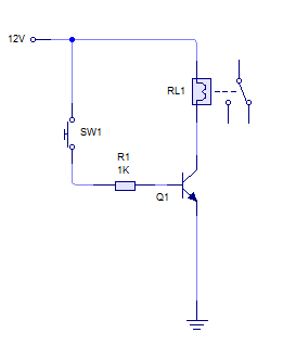
A relay is activated by grounding the low side using an NPN transistor. A pushbutton is intended to operate the transistor, thereby energizing the relay for approximately 500 milliseconds before deactivating it, while ignoring any continuous button press. Although...
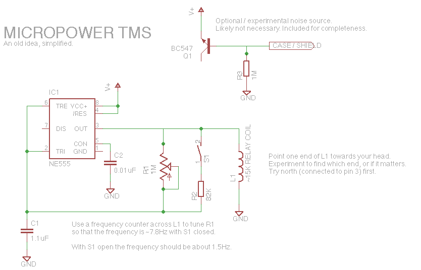
Let's face it, not every day is the greatest. Sometimes, one may not feel like doing much of anything. Wouldn't it be nice if there was a way to change brain waves at the push of a button? Transcranial...
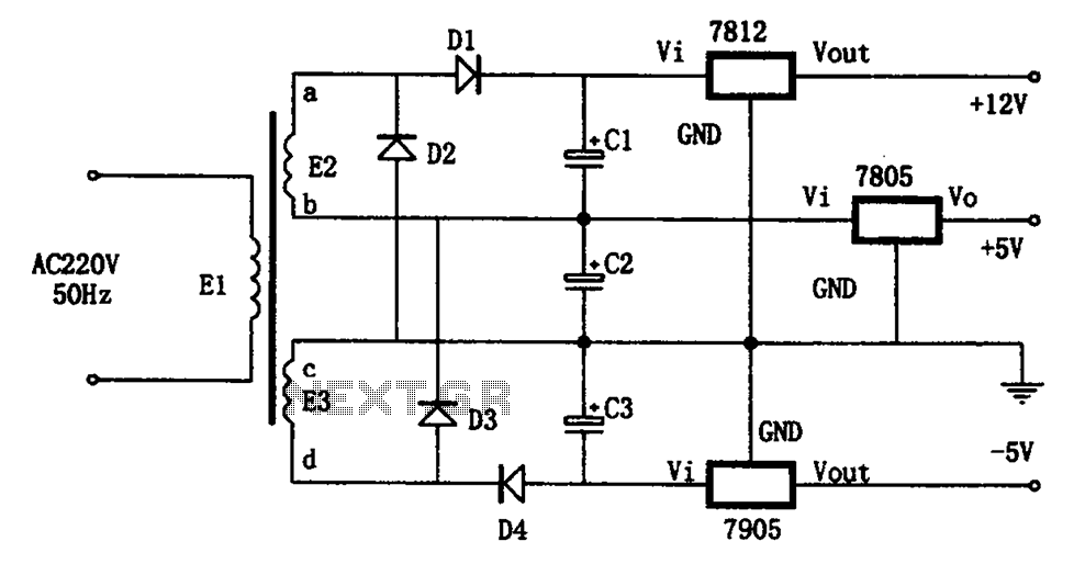
The circuit illustrated in the figure represents a specialized power supply configuration. It is straightforward in design and can be constructed using two identical secondary windings to generate three distinct DC voltage outputs: +5V, -5V, and +12V. The circuit...
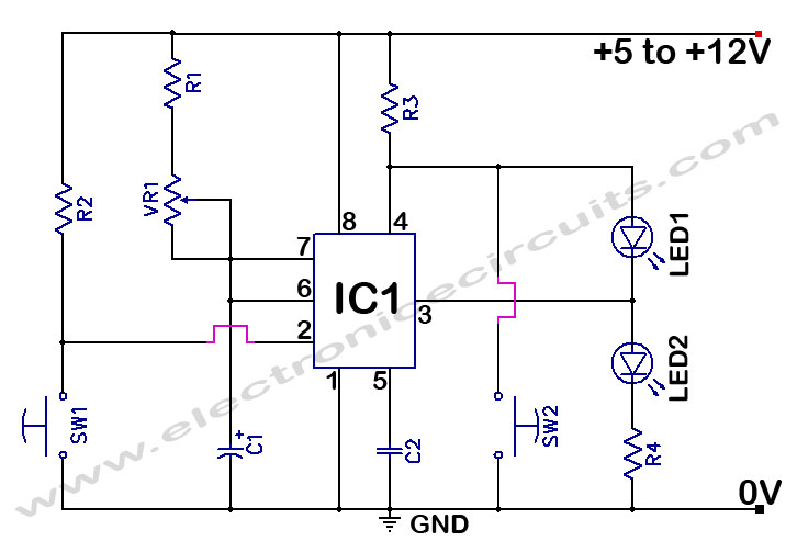
The 555 Timer Time Delay Circuit uses LEDs to visually indicate the status of the circuit at any moment. The operation begins when the reset switch, SW2, is activated. The 555 Timer is a versatile integrated circuit widely used for...

The FM modulator circuit is a straightforward FM modulation design utilizing the IC 555, where the resulting modulated signal is dependent on the frequency of the input signal. The output signal is stable and of good quality, eliminating the...