
Tactile sensors Motor controller

This circuit represents a photovore design that utilizes tactile sensors to enable reactive behaviors in response to environmental stimuli. The core components include two tactile sensors, which play a crucial role in detecting obstacles. When an object is encountered, the sensors trigger a response in the motors, allowing the device to maneuver away from the obstacle.
The behavior of the motors is primarily governed by the capacitors C1 and C2. These capacitors determine the duration of the motor reversal after a tactile sensor is activated. Increasing the capacitance of C1 and C2 will result in a longer reversal time, causing the device to turn more sharply after encountering an object. Conversely, decreasing the capacitance will lead to a more subtle turn.
The circuit employs standard resistor values of 1MΩ for most applications, ensuring that the current flow is appropriately limited. This design is tailored for individuals with advanced knowledge of BEAM robotics, as it incorporates modifications that can enhance the behavior of the photovore. For beginners, an alternative circuit such as the iVore may be more suitable.
To drive the motors effectively, it is recommended to stack at least two 74AC240 integrated circuits. This configuration allows for sufficient power delivery to the motors. If additional power is required, a third 74AC240 can be added to the stack. The circuit is powered by a battery pack, with a common configuration being four AAA batteries, which provide a compact and accessible power source.
The components required for this circuit include:
- Resistors: 6 x 1MΩ and 2 x 1.5MΩ.
- Capacitors: 2 x 1µF (for C1 and C2) and 6 x 0.22µF.
- Integrated Circuits: 2 or more 74AC240.
- Tactile Sensors: 2 units.
For sourcing components, reputable suppliers such as Digikey offer the necessary parts, ensuring availability for building the circuit. The tactile sensors are critical for the functionality of the photovore, and tutorials may provide additional insights into their implementation.It's basically a photovore with a couple tactile sensors. It's rather complex but can give neat behaviors with modifications to the circuit. At this point I don't have any plans to give more information on this circuit so your on your own. C1 and C2 values C1 and C2 are the capacitors that control how long each motor will reverse after the tactile sensor is triggered. Increasing the value will cause your bot to turn more after bumping an object. Decrease and it will turn less. The layout All resistors are 1M unless labeled otherwise. All capacitors are .22uF unless labeled otherwise. This circuit is more for advanced BEAMers so if your a newbie to BEAM I would recommend the iVore circuit.
I may get some more info on the circuit on the web but no plans yet. In order to drive your motors you'll need to stack at least two 74AC240's on top of each other. I used two 240's to drive my cassette motors but if you still don't get enough power out of your motors with two you could stick another one on top. Battery pack 1 Just about everywhere. I used 4 AAA's on mine. N/A Motor 2 Broken electronics - walkman, cd player, pager... Or new at: Solarbotics BG Micro All Electronics Goldmine Electronics See products page Browse catalog Browse catalog Browse catalog 1M Resistor 6 Digikey 1MEBK-ND 1.5M Resistor 2 Digikey 1.5MEBK-ND 1uF Capacitor (C1 & C2) This is just a suggested size for C1 and C2.
See notes for more info. 2 Digikey P2105-ND .22uF Capacitor 6 Digikey P4966-ND 74AC240 2+ Digikey 74AC240PC-ND Tactile Sensor 2 See tutorial 🔗 External reference
Related Circuits

The circuit is constructed using two 555 timer integrated circuits (ICs), designated as U1 and U2. U1 is configured as a variable duty cycle oscillator with a fixed time period of approximately 0.1 seconds. The duty cycle can be...
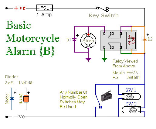
These are two easy-to-build relay-based alarms. They can be used to protect a motorcycle, but they have many additional applications. When using relays with 6-volt coils, they can safeguard a classic bike. Both alarms are compact, with completed boards...
The I/O board incorporates 16-bit resolution voltage analog inputs and outputs, along with a 4-20mA current loop transmitter and receiver for microcontroller applications. The document discusses amplifier circuits and schematics, including a signal conditioning variable gain amplifier, analog filter,...
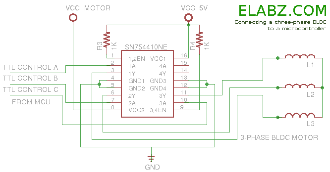
Arduino sketch and other useful information about driving a brushless DC motor, such as a DVD drive spindle motor, using Arduino or another microcontroller. The task of driving a brushless DC motor, particularly one sourced from a DVD drive spindle,...
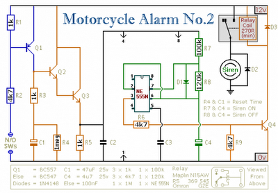
Any number of normally-open switches may be utilized. Install "tilt" switches that close when the steering is moved or when the bike is lifted off its side-stand or pushed forward off its centre-stand. Employ micro-switches to secure removable panels...
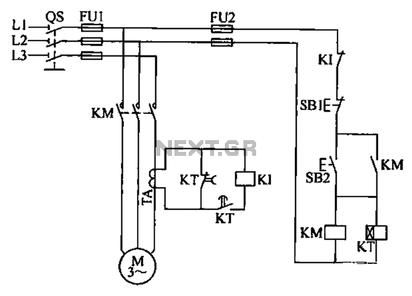
A three-phase electric motor overcurrent protection circuit. This example circuit utilizes a transformer to monitor the current, ensuring that the currents in the three-phase motor do not exceed normal operating levels. When the current exceeds the set threshold, the...