
Taming the GTX 900 MHz

The GTX 900 MHz radios are designed with specific operational parameters and alignment points that ensure optimal performance within their intended frequency ranges. The issue of erratic output power is primarily attributed to the lack of calibration for out-of-band frequencies. The radio's firmware utilizes preset values for power and deviation adjustments, which are effective within the designated bands but fail outside of them. This limitation necessitates the implementation of a manual power control adjustment, which allows users to stabilize output power across amateur frequencies where the built-in calibration does not apply.
To implement a manual power control adjustment, a potentiometer can be integrated into the radio's circuitry, allowing the user to fine-tune the output power as needed. This modification should be approached with caution, ensuring that it does not interfere with the radio's existing digital control mechanisms. The addition of this control not only enhances usability for amateur radio operators but also mitigates the frustrations caused by the inherent limitations of the radio's design.
Furthermore, any modifications should be documented thoroughly to assist other users who may encounter similar issues. It is advisable to maintain a comprehensive log of changes made to the radio, including any adjustments to the alignment points and the results of those adjustments. As the community continues to share experiences and solutions, the understanding of the GTX radios' behavior in amateur applications will improve, leading to better techniques for managing output power and deviation settings.Many of us who use GTX 900 MHz radios to work amateur repeaters are well aware of the erratic output power problem. You go through the complete board replacement procedure, adjusting the deviation and output power, and everything looks great on the test frequencies of 896 through 902 MHz, and 935 through 941 MHz.
After all, these are the bands that the radio was designed for and specified to work in. Then you program in and transmit on some amateur frequencies and you find various output power levels of 0. 8 watts, 12 watts (where you aligned the radio`s output power), or 19 watts. On one radio I have, I would get 12 watts on 902. 4125 MHz and 902. 4875 MHz (two repeater input frequencies), 19 watts on 927. 6000 MHz (a simplex frequency), 0. 8 watts on 927. 5000 MHz (another simplex frequency) and 19 watts on 927. 4125 MHz and 927. 4875 MHz (two repeater output frequencies). Depending on the radio, the power remains controlled on some channels, while others are always erratic.
Naturally, the radio still works just fine on the commercial frequencies it was designed for. The GTX radios (as well as some other Motorola products) have 16 alignment points (sub-bands or frequencies) for power and deviation that are adjusted during board replacement or calibration procedures. In the case of the 900 MHz GTX mobile, there are eight of these points, in 1 MHz increments, at frequencies between 895.
5 and 902. 5 MHz, and between 934. 5 and 941. 5 MHz. When the radio transmits in these bands, the appropriate values for that frequency are pulled from the table and used to program the output power and deviation circuits. A problem occurs when an out-of-band frequency is used (902 - 935 MHz); the radio (or RSS) has no idea what value to use, because the sub-bands aren`t calibrated for that frequency range.
If it uses zero, the radio puts out 0. 8 watts. If it uses a high value, the radio puts out 19 watts. I have not yet figured out if the RSS determines the power and deviation values and sends that information to the radio during programming, or if the radio itself makes the determination of which values to use as the channel is changed. That`s being saved for a future project. Since the radio is incapable of controlling the output power properly when used in the amateur band, I`ve finally given in and decided to add a manual power control adjustment, so the output power is relatively constant across the frequencies of interest.
There`s a similar article about doing this to a MaxTrac on this page. The MaxTrac can also be modified to control deviation in the same way, by adding a pot. However the deviation in the GTX is controlled by the microprocessor which sends a digital value directly to the audio IC, rather than through external analog circuitry. So you can not add a pot to control deviation on the GTX radios. I have tried using a "magic" code plug that, on some radios, seems to control the output power better, but even that has failed to produce consistent power levels, and on one radio it worked fine until I added a few more channels, then I was back to uncontrolled output power.
I know I`m not alone in this experience; Dave N1OFJ has a radio with the same problem and he will be doing this modification very soon. Another person also initially reported success with the "magic" code plug, but after he enabled scan on some channels, the output power reverted to its inconsistent behavior.
I recently repaired a GTX mobile radio that was displaying E06 all the time. I went through the entire board replacement procedure and the radio met all specifications. After programming it with amateur frequencies, including two scanning modes, the output power was either under 1 watt or over 15 watts, where it was previously making 12 watts. I removed the two modes from the scan list and disabled scanning, wrote the code plug back to the radio, and now it makes 12 watts on all amateur freque
🔗 External reference
Related Circuits
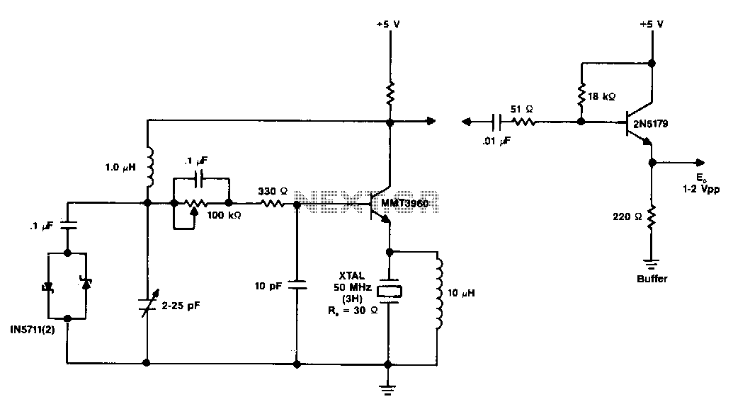
The diagram illustrates a 50 MHz oscillator functioning at its third harmonic. The collector load resistor R1 has been increased due to the rise in the quartz crystal's internal series resistance Rs, which escalates with frequency in the VHF...
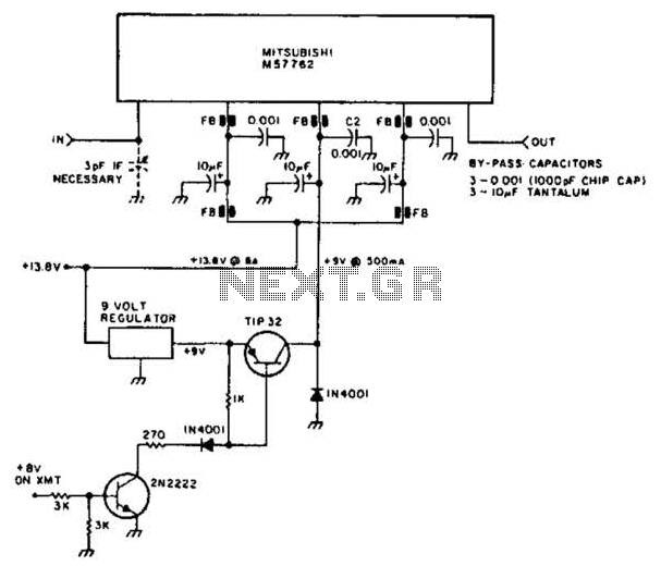
Using a Mitsubishi M57762 amplifier module, this amplifier delivers 20 W output at 1296 MHz. A single 12 V nominal power supply can be used. The Mitsubishi M57762 is a high-performance RF amplifier designed for applications requiring significant power output...
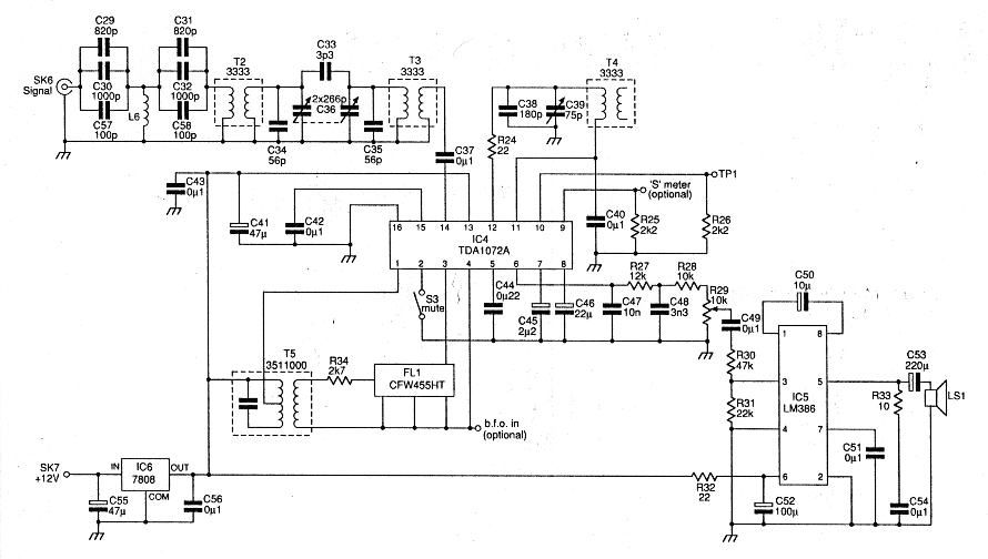
Before starting on the receiver side of the Chatterbox, a final review of the transmitter is necessary. The Chatterbox transmitter is constructed separately, as many builders may wish to use it alongside an existing receiver operating at 1.8 MHz....
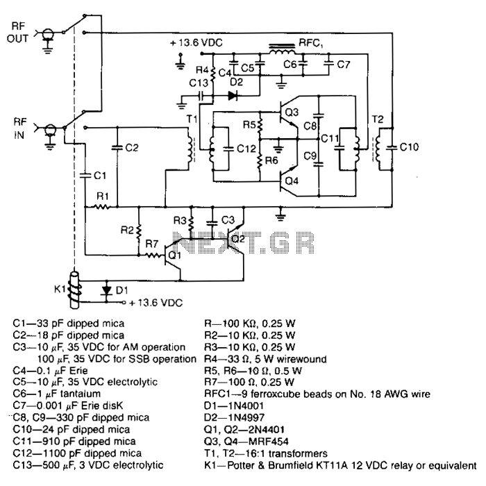
This amplifier delivers a nominal output power of 140 watts peak envelope power (PEP) when fed with input levels as low as 3 watts. Both the input and output transformers feature a 4:1 turn ratio and a 16:1 impedance...
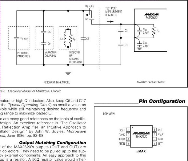
The MAX2620 integrates a low-noise oscillator with two output buffers in a cost-effective, plastic surface-mount, ultra-small uMAX package. This device combines functions that are typically achieved with discrete components. The MAX2620 is designed for applications requiring precise frequency generation with...
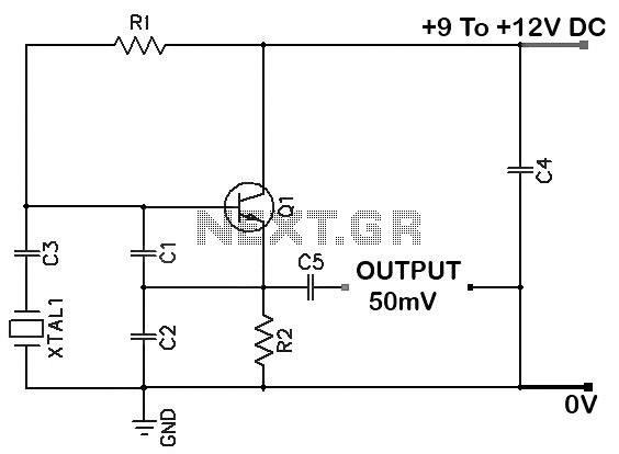
Colpitts 1 MHz to 20 MHz Crystal Oscillator Circuit. This is a simple Colpitts crystal oscillator for frequencies ranging from 1 to 20 MHz. The parts list includes: R1 - 220 kΩ, R2 - 1 kΩ, C1 - 82...