
MAX2620 10mhz To 1050mhz Integrated Rf Oscillator With Buffered Outputs

The MAX2620 is designed for applications requiring precise frequency generation with minimal noise. It features a low-noise oscillator that provides stable and reliable frequency output, making it suitable for RF applications, signal processing, and other electronic circuits where signal integrity is paramount.
The oscillator's design minimizes phase noise and jitter, which are critical parameters in communication systems. The two output buffers are configured to drive capacitive loads while maintaining signal integrity, ensuring that the output signals remain clean and distortion-free.
The uMAX package offers significant advantages in terms of size and ease of integration into compact circuit designs. This small form factor allows for high-density layouts, which are essential in modern electronic devices where space is at a premium.
Additionally, the MAX2620 is characterized by its low power consumption, making it an ideal choice for battery-operated devices. The device operates over a wide voltage range, providing flexibility in various applications. Its robust performance and ease of use make the MAX2620 a valuable component in the design of advanced electronic systems.The MAX2620 combines a low-noise Oscillator with two output Buffers in a low-cost, plastic surface-mount, ultra-small uMAX package. This device integrates functions typically achieved with discrete co.. 🔗 External reference
Related Circuits
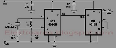
This circuit is designed for accurate time-base generation utilizing the commonly available 3.5795 MHz crystal, which is frequently used in telecommunication equipment. A crystal-based oscillator combined with a divider IC chain or a similar circuit, such as an ASIC,...
This circuit was featured in the "design ideas" section of EDN's March 5, 2007 issue. It is a relatively simple circuit that allows investigation into how the inductance of a toroid (or any core) is affected by saturation, which...
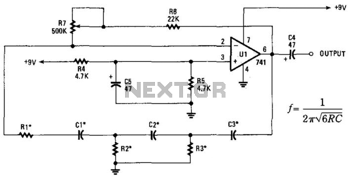
This phase-shift oscillator is suitable for audio oscillator applications. Adjust R7 to achieve a good sine wave. An amplifier gain of 29 is necessary for oscillation. If C=C1=C2=C3 and R=R1=R2=R3: Typically, R will range from 1 to 100 kOhm...
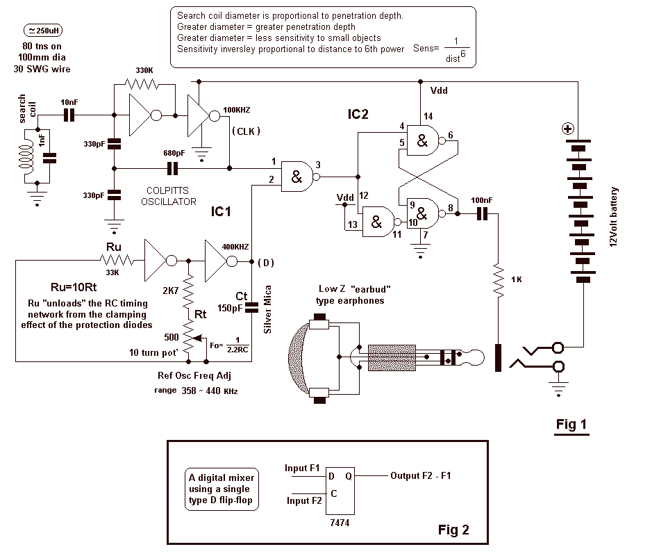
The circuit uses two CMOS ICs. IC1 uses inverters connected as a Colpitts oscillator of 100KHz; the LC frequency determining elements being the search coil and parallel resonating capacitor. An 80 turn close wound 30swg 100mm diameter coil will...
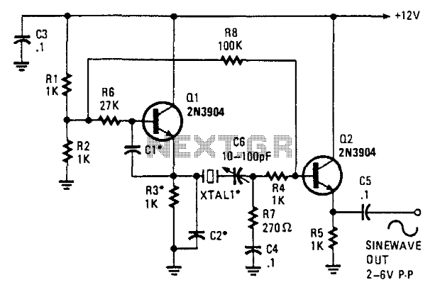
This oscillator employs two transistors and operates the crystal in its fundamental mode. Capacitors CT and C2 should be approximately 2,700 pF for 1 MHz, 680 pF for 5 MHz, and 330 pF for 10 MHz. A capacitance of...
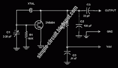
This circuit is a conventional Pierce-type oscillator that utilizes a JFET. It operates with fundamental mode crystals, offering decent performance and reliability when a low noise JFET is employed. The feedback is regulated by the capacitance of C1 from...