
1.8MHz AM transmitter and receiver
The Chatterbox transmitter and receiver system is designed to provide effective communication for local amateur radio operations. The modular approach allows for flexibility in integration with existing equipment, making it suitable for various configurations. The use of the TDA1072A chip ensures cost-effectiveness while maintaining adequate performance for the intended application. Careful attention to the construction of filters and tuning components is essential for optimal signal quality. The incorporation of additional features from the TDA1072A chip can enhance functionality and provide users with more control over their reception capabilities. Overall, this design serves as a practical solution for amateur radio enthusiasts seeking to establish reliable communication within their local networks.Before starting on the receiver side of the` Chatterbox`, we ought to take a final look at the transmitter itself. The Chatterbox transmitter is built separately, because many constructors will want to use it in conjunction with an existing receiver on 1.
8MHz. It`s been assumed that an existing antenna tuner and low-pass filter unit will be used w ith the transmitter. However, if you intend to use the complete transmitter and receiver combination as a `stand alone` unit, it will be necessary to use a suitable low-pass filter to reduce potential harmonics. A filter of this sort can be built into the transmitter, or it can be an outboard type used in conjunction with a small antenna tuner.
What the individual constructor does of course, will depend on the size of casing and whether or not the project is built as separates or as one small unit. With the change-over switching described in the previous article, the transmitter can be used with any 1.
8MHz receiver. If you don`t have a suitable set, you can add a simple single board receiver of the sort described here. However, bear in mind that the receiver is not a DX model and it`s designed for using the Chatterbox combination in local a.
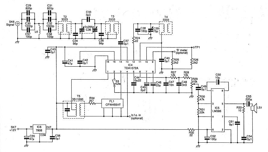
m. nets. The receiver section is based on the TDA1072A a. m. receiver i. e. This is an inexpensive chip which performs all the functions of an a. m. receiver between the antenna and the audio stages. The TDA1072A`s sensitivity and signal handling capabilities are such that it`s suitable for this application. The i. e. also supports several features not used in this design. Some of the features are made available on the p. c. b. , should you wish to incorporate them in the receiver. For example, the chip provides an S-meter output, a muting facility and a buffered oscillator output for driving a frequency counter.
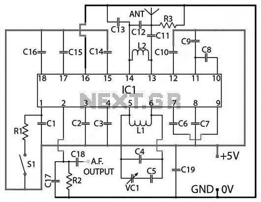
The circuit is shown in Fig. 2. 1, and it closely follows the manufacturer`s specification sheet. The incoming signal is filtered with a high-passfilter, L6 (wound on a toroid) and associated capacitors, and a two stage band-pass filter, comprising of T2 and T3. The high-pass filter was included because the receiver operates close to the medium wave broadcasting band.
Winding the toroid for L6 is a simple job and it only requires a little concentration for a neat job. All you need to do is wind 24 turns of 0. 4 or 0. 5mm enamelled copper wire on a T37-2 core. I have a local commercial broadcasting station at the top end of the medium waveband that can light bulbs in my location in Rochdale!
The high-pass filter was included to kill the pop music breakthrough. The band-pass filter has manual tuning provided by a polyvaricon capacitor, C36, to peak the wanted band signals and reduce the out-of-band signals. The band is tuned using a variable capacitor, C39, in conjunction with T4. Although the TDA 1072A was designed for varicap tuning, this arrangement allows for very stable tuning over the band.
The variable capacitor, C39, is a standard value, 75pF, (a 100pF may be used as an alternative) which more than covers the whole band. This tuning capacitor is mounted directly on the printed circuit board. The ground connection on C39, is made through the mounting nut to the p. c. b. To avoid any problems with poor connections, I also added a wire between the tag to the moving vanes and the ground plane on the top of the printed circuit board.
The i. f. at455kHz, is filtered by using a CFW455HT ceramic filter and an i. f. transformer, T5, placed between the mixer output, pin 1, and the i. f. amplifier, pins 3 and 4. It`s possible to inject a b. f. o. signal at pin 4, to make the receiver available for c. w. and s. s. b. reception. Several radio amateurs have used this i. e. to make a c. w. and s. s. b. receiver. I tried injecting a 455kHz signal at pin 4, but found that it triggered the internal a. g. c. This reduced the overall gain of the receiver, to what I considered to be an un 🔗 External reference
Related Circuits

This schematic represents a radio receiver circuit based on the TDA7088T, which is suitable for use in mono portable and pocket radios. The TDA7088T is a bipolar integrated circuit designed to operate with a minimal number of peripheral components...

The individual was not inclined to create and program the timing controller for the PCB laser printer. They recalled having a laser tag gun that had been misaligned during a previous disassembly. The device in question is a Nerf...
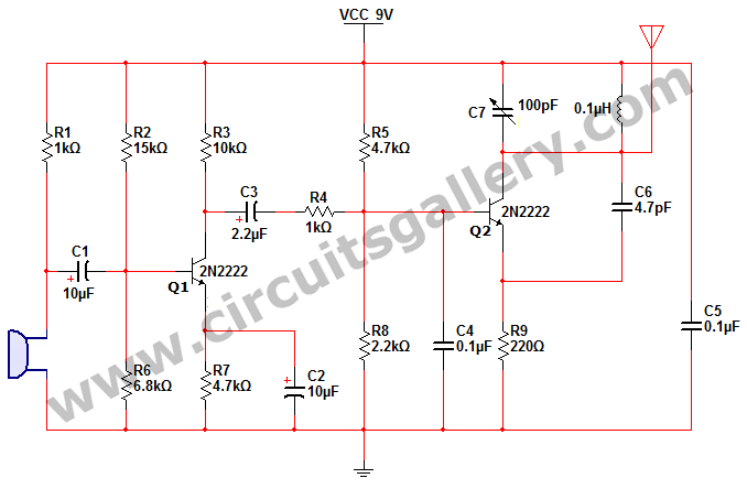
This is a simple 2N2222 transistor-based FM transmitter circuit that operates within the FCC (Federal Communications Commission) limits, meaning no license is required for its use. FM stands for Frequency Modulation, which is a method of transmitting radio frequency...
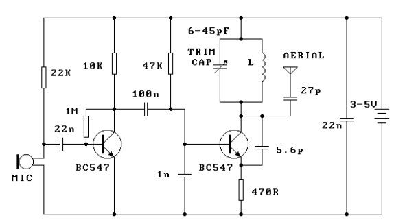
This FM transmitter circuit is simple and provides acceptable transmission. The signal transmitted from this FM transmitter circuit can be received at... This FM transmitter circuit utilizes a few basic components to generate frequency-modulated signals suitable for short-range transmission. The...
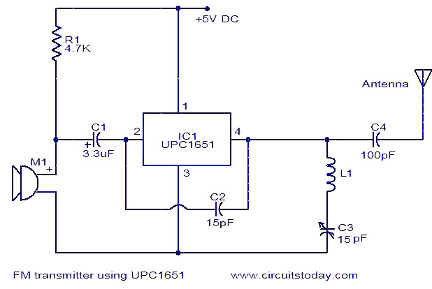
The circuit diagram of an FM transmitter utilizes the IC UPC1651, which is a wideband UHF Silicon MMIC amplifier. This integrated circuit features a broad frequency response of up to 1200 MHz and a power gain of up to...
PARTS LIST C1 0.22 µF (224) C2 22nF (223) C3 10nF (103) C4 27pF C5 22pF C6 3.3nF (332) C7 180pF (181) C8 330pF (331) C9 3.3nF (332) C10 150pF (151) C11 82pF C12 68pF C13 220pF (221) C14...
Warning: include(partials/cookie-banner.php): Failed to open stream: Permission denied in /var/www/html/nextgr/view-circuit.php on line 713
Warning: include(): Failed opening 'partials/cookie-banner.php' for inclusion (include_path='.:/usr/share/php') in /var/www/html/nextgr/view-circuit.php on line 713